


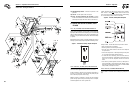

1.1 UNPACKING
• Set the palleted carton on a rigid flat surface.
• Remove staples along bottom of carton that fasten carton to
pallet. Open carton from top.
• Remove all packaging material.
• Remove separate accessory box.
• Lift carton off the generator.
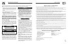
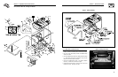
• Remove generator from shipping pallet by removing bolts
through the shipping brackets.
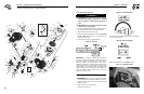
Figure 1 - Bracket Removal
1.1.1 ACCESSORY BOX
Check all contents. If any parts are missing or damaged locate an
authorized dealer at 1-800-333-1322.
Contents include:
• Owner’s Manual
• Bolt-on tubular handle
• Wheel Axle
• 2 – Pneumatic Wheels
• 2 – Axle Bracket Assemblies
• 2 – Washers
• 2 – Wheel Spacers
• 2 – Cotter Pins
• Bolt-on Foot
• 6 – Carriage Bolts, Washers, Nuts
• Battery Charge Cable
• Spark Plug Wrench
• 2 Spark Plugs.
• Air Filter
• Pre-cleaner
1.2 ASSEMBLY
The generator requires some assembly prior to using it.
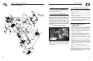
1.2.1 ASSEMBLING THE WHEEL KIT
The wheel kit is designed to greatly improve the portability of the
generator. A socket wrench with a 9/16” socket, a 1/2” socket, a
1/2” wrench and a pair of pliers are the tools that will be needed
for assembly of the wheel kit.
Note:The wheel kit is not intended for over-the-road use.
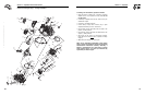
• Refer to Figure 2 shown on opposite page and install the wheel
kit as follows:
• Place the generator on a hard flat surface.
• Stand at the engine end of the unit and gently tilt the generator
forward, high enough to place wooden blocks beneath the
cradle. This will allow space to install the wheel assemblies.
• Attach an axle bracket assembly with attached sleeve to either
side of the frame. Ensure the sleeve faces outward.
• Slide the axle through the sleeves on the axle brackets.
• Slide one wheel with flat washer to the outside and a spacer to
the inside onto each end of the axle. Make sure the air inflation
valve on the wheel is facing outward.
• Insert retaining pins and using pliers, bend out the ends to
prevent the pins from falling out of the axle. Remove the
wooden blocks.
1.2.2 ASSEMBLING THE HANDLE
• Attach the handle by aligning one side of the handle on the
cradle, then spread the handle around the cradle and let it
spring into place. Secure the handle to the frame using the
5/16’ hex head bolts provided. Check each fastener to ensure
that it is secure.
• Using the handle, lift the unit high enough to place wooden
blocks under the unit. Attach the front support foot to the
underside of the cradle using the 3/8” carriage bolts provided.
• Remove the shipping brackets from the cradle, if you have not
already done so.
4
Section 1 – General Information
Commercial-Industrial-Residential Portable Generator System
Shipping
Bracket
(x4)
33
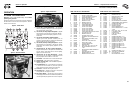
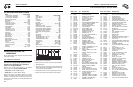
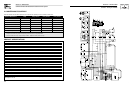
ITEM PART NO. QTY.DESCRIPTION
1 057058 4 SCREW HHC M6-1.0 X 55
2 0D5315 4 RUBBER TANK MOUNT
3 0D4570 1 CAP, FUEL WITH GAUGE & VENT
4 0D22850SRV 1 KIT, FUEL TANK
5 045771 4 NUT HEX M8-1.25
6 022129 10 WASHER LOCK M8-5/16
7 022145 14 WASHER FLAT 5/16
8 0D4565 1 BRACKET BATTERY
9 0D3545 2 BOLT,BATTERY J-BOLT
10 022287 2 SCREW HHC 1/4-20 X 3/4 G5
11 022473 2 WASHER FLAT 1/4
12 022097 2 WASHER LOCK M6-1/4
13 022127 2 NUT HEX 1/4-20
14 0388040AK0 1 BATTERY CABLE, RED
15 0D4575 1 BATTERY U1
16 0D5202 1 NUT WING 5/16-18 BRASS
17 0D5199 4 WASHER FLAT 5/16 BRASS
18 029809 1 NUT HEX 5/16-18 BRASS
19 0C3168 1 5/16 SPECIAL L/WASH
20 0D5198 1 SCREW HHC 5/16-18 X 1.5 BRASS
21 0E0317 1 BRACKET FRONT FOOT (15 kW)
0D2498 1 BRACKET FRONT FOOT (12.5 kW)
22 027007 2 VIB MOUNT
23 0D5303 4 WASHER FLAT .25ID X 1"OD
24 042909 2 SCREW HHC M8-1.25 X 30
25 090388 4 SCREW HHTT M6-1.0 X 12
26 064101 6 NUT LOCK FL 3/8-16
27 039214 6 BOLT CARR 3/8-16 X 1
28 0D9165 1 AXLE, 3/4"DIA X 30" (15 kW)
0D2496 1 AXLE, 3/4"DIA X 27.25" (12.5 kW)
ITEM PART NO. QTY.DESCRIPTION
29 045900 2 WASHER FLAT 3/4" (15 kW)
045900 4 WASHER FLAT 3/4" (12.5 kW)
30 0D7668 2 12.3" PNEUM WHEEL 3/4" AXLE
(15 kW)
0D2495 2 10" PNEUM WHEEL 3/4" AXLE
(12.5 kW)
31 0D4999 2 PIN COTTER 1/8 X 1-1/4
32 0D4044 2 BRACKET, WHEEL SPACER
33 0D3700 4 NUT FLANGE M6-1.0 NYLOK
34 0D2497 1 HANDLE
35 022532 4 SCREW HHC 5/16-18 X 2-1/2 G5
36 027028 6 NUT LOCK HEX 5/16-18 NYLON
INSERT
37 0D2271 1 FRAME
38 052762 4 SCREW HHC M5-0.8 X 45 G8.8
39 051713 8 WASHER FLAT M5
40 049226 4 WASHER LOCK M5
41 051716 4 NUT HEX M5-0.8
42 050190 2 WASHER FLAT 1"
43 078299 1 BUSHING TANK DEXTOR
44 080270 1 VALVE, PLASTIC TANK
45 0D5142 1 AIR DEFLECTOR
46 096021 2 GROMMET .75 X .06 X .50
47 048031C 2 CLAMP HOSE BAND ¼
48 030340 18" HOSE ¼ ID
49 075763 1 BOOT BATTERY CABLE
50 075763A 1 BOOT STARTER CABLE
51 0E0318 2 SPACER, AXLE (15 kW)
52 030795 2 SCREW HHC 5/16"-18 X 1"
Section 7 — Exploded Views and Parts Lists
Commercial-Industrial-Residential Portable Generator System
Frame, Handle & Wheel Kit – Drawing No. 0E0695A