


4
T
T
H
H
E
E
P
P
O
O
W
W
E
E
R
R
S
S
E
E
E
E
K
K
E
E
R
R
1
1
1
1
4
4
R
R
e
e
f
f
l
l
e
e
c
c
t
t
o
o
r
r
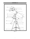
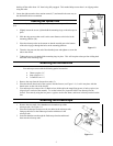
The PowerSeeker is a Newtonian reflecting telescope that comes on an equatorial mount. This section instructs
you on the proper assembly and use of your PowerSeeker telescope, which is shipped in one box, containing all the
parts you need to assemble it. Unpack and lay out all of the parts in a large, clear area where you’ll have room to
work. Keeping track of the parts, use the list below and the telescope diagram to confirm you have, and can identify
each part.
PowerSeeker 114
1. 5x24 Finderscope 12. Accessory Tray
2. Eyepiece 13. Center Support Brace
3. Focuser Draw Tube 14. Tripod Tightening Screws
4. Tube Ring Locking Bolt 15. Counterweight
5. Optical Tube 16. Counterweight Bar
6. Collimation Screws (not shown) 17. R.A. Slow Motion Control
7. Declination Slow Motion Control 18. Equatorial Mount
8. Latitude Adjustment Screw 19. Declination Locking Screw
9. Tripod Mounting Head 20. Mounting Platform
10. Tripod Leg 21. Focuser
11. Equatorial Head Mounting Screw 22. Finderscope Bracket
A
A
s
s
s
s
e
e
m
m
b
b
l
l
i
i
n
n
g
g
Y
Y
o
o
u
u
r
r
T
T
e
e
l
l
e
e
s
s
c
c
o
o
p
p
e
e
To set up the tripod, locate the equatorial mount (18), the tripod legs (10), and the tripod mounting head (9).
1. Slide the two top portions of each tripod leg around the sides of each flange on the tripod mounting head (9).
Make sure that the tripod center support brace hinges (13) are located on the inside of the each leg.
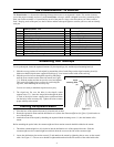
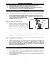
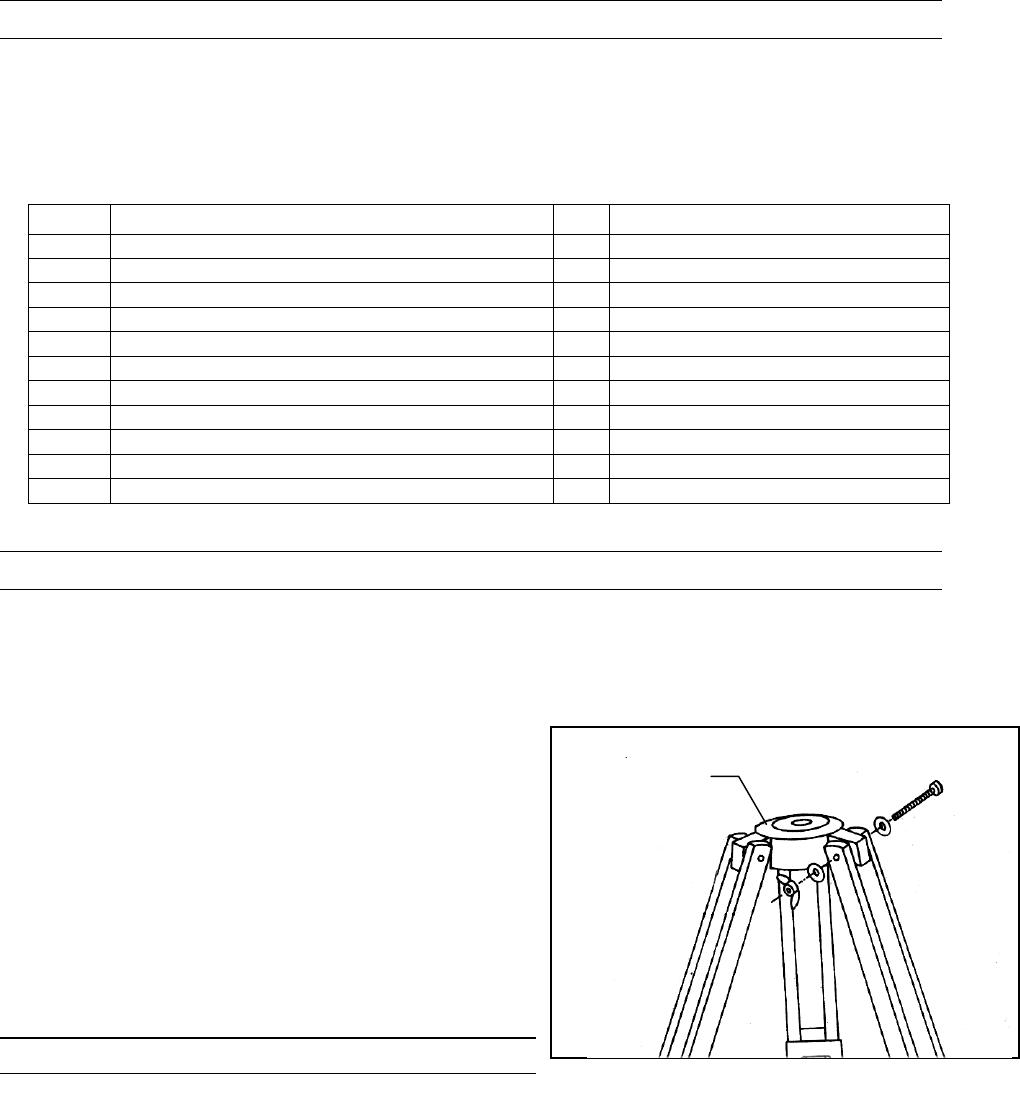
2. Slide the provided screws through the tripod leg and flange,
until the screw extends out the other side mount (see Figure
1-2). Slide the washer and the nut over the screw and tighten.
This can be left slightly loose, to allow for positioning the
legs later, when attaching the accessory tray.
You are now ready to attach the tripod accessory tray.
3. The tripod tray fits over the holes in the tripod's center
support brace (13). Insert the winged bolts through the holes
in each of the tripod center support braces and thread them
into the holes in the accessory tray. Tighten all bolts to ensure
proper stability to the mount.
A
A
t
t
t
t
a
a
c
c
h
h
i
i
n
n
g
g
t
t
h
h
e
e
E
E
q
q
u
u
a
a
t
t
o
o
r
r
i
i
a
a
l
l
M
M
o
o
u
u
n
n
t
t
1. Place the base of the equatorial mount (18) into the hole on the top of the tripod mounting head (9).
2. Rotate the equatorial mount until the declination axis (where the counterweight bar (16) goes) is positioned over
one of the tripod legs.
3. Attach the mount to the tripod by threading the equatorial head mounting screw (11) into the bottom of the
mount
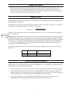
Before attaching the optical tube, the counterweight and slow motion controls should be added to the mount:
1. Thread the counterweight bar (16) clockwise into the declination axis of the equatorial mount. Slide the
counterweight over the counterweight bar and lock down the screw on the side of the counterweight.
2. Locate the declination slow motion control (7) and attach to the mount by tightening the set screw on the control
cable. See Figure 1-3. The set screw should be tightened down hard on the flat surface of the cable holder after
Tri
p
od
Mounting Head
(
9
)
Figure 1-2