


6
PROCEED TO YOUR FAN’S CONTROL FEATURE SECTION FOR INSTALLATION/OPERATING INSTRUCTIONS:
4-SPEED - PAGE 7 | INTELI•TOUCH2 - PAGE 9
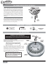
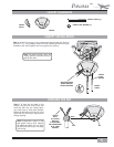
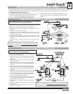
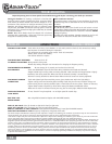
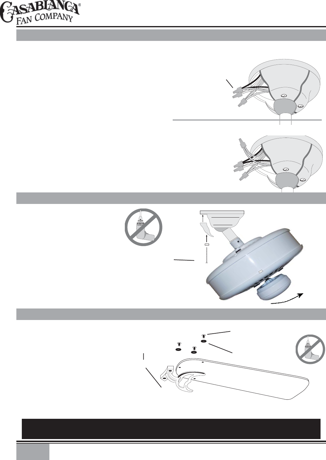
Install the assembled blade and
blade holder to the motor.
Hand tighten securely.
Repeat for each assembly.
FELT WASHER
(3 PER BLADE)
BLADE HOLDER
SCREW
(2 PER BLADE
HOLDER)
WARNING: To reduce the risk of personal injury, do not bend blade holders when installing, bal-
ancing, or cleaning. Do not insert foreign objects between rotating fan blades.
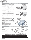
Step 10.
Attach the blades to the blade
holders with the three blade
screws and felt washers provided
for each blade.
Hand tighten securely.
BLADE
BLADE SCREW
(3 PER BLADE)
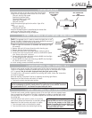
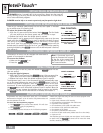
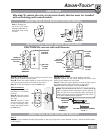
NOTE: See Page 8 for additional wiring information.
Step 6a. Attach the fan wires to the ceiling fi xture outlet
box wiring by twisting the bare ends of the wires together
and then securing with a wire nut. Test that the connection
is secure by pulling on the wire nut. Connect in this order:
Step 6b. Pull Chain or W-41 Wiring Connections
• GREEN leads from mounting plate and fan to GROUND
conductor of power source. Secure with wire nut.
• WHITE wire from fan to white NEUTRAL wire in ceiling
fi xture outlet box. Secure with wire nut.
• BLUE wire and BLACK power wire from fan to BLACK power
wire in ceiling outlet box. Secure with wire nut.
Step 6c. W-81 Wiring Connections
• GREEN leads from mounting plate and fan to GROUND
conductor of power source. Secure with wire nut.
• WHITE wire from fan to white NEUTRAL wire in ceiling
fi xture outlet box. Secure with wire nut.
• BLACK power wire from fan to RED wire from W-81 in ceil-
ing outlet box. Secure with wire nut.
• BLUE wire from fan to YELLOW wire from W-81 in ceiling
outlet box. Secure with wire nut.
2 WHITE WIRES
2 BLACK & BLUE
D1-OPTION WIRES
(WITHOUT W-81)
WIRE NUT
W-81 CONNECTIONS
3 GREEN WIRES
3 GREEN WIRES
2 WHITE WIRES
BLACK & RED
WIRES
BLUE & YELLOW
WIRES
PULL CHAIN OR
W-41 CONNECTIONS
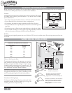
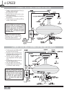
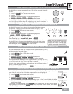
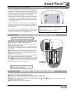
Step 7. Tuck the wires into the canopy
with the wire nuts pointed upwards, so
that the WHITE and BLACK wires are on
opposite sides of the canopy and all wires
are clear of the canopy opening.
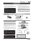
Step 8. Install canopy hatch with the
last canopy screw and lock washer. To
do this, tilt the fan body away from the
hatch opening.
Tighten the screws fi rmly by hand only,
TILT THE
FAN TO
INSTALL
LAST
CANOPY
SCREW
CANOPY
HATCH
CANOPY
SCREW
LOCK
WASHER
Step 9. Straighten the fan, then check
to ensure that there is no movement be-
tween the canopy and ceiling or Hang-Tru
ball and top support shaft.
CANOPY HATCH INSTALLATION
CANOPY ELECTRICAL CONNECTIONS
BLADE HOLDER & BLADE ASSEMBLY