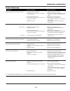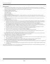
3
Models GN301502AC and GN30C502AC
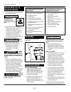
STARTING
1. Check oil level and fuel.
2. Remove all electrical loads from the
generator.
3. Set the switch to the ON position.
4. Move the choke/run switch to the
choke position.
5. Pull the starter rope with a brisk
smooth motion.
6. Move the choke/run switch to the
run position.
7. After each start up, allow engine to
run 2-3 minutes with no load.
Engine speed is
preset to provide
proper output voltage. Never attempt to
modify or adjust engine speed or output
voltage.
ENGINE BREAK-IN
After initial start-up, the engine should
be broken in according to the
manufacturer’s instructions. Refer to the
engine manual for the proper break-in
procedure.
GENERATOR SHUT OFF
1. Remove all electrical load devices
from the generator.
2. Allow the engine to run for 2-3
minutes with no electrical loads.
3. Set the switch to the OFF position.
This will stall the engine.
!
CAUTION
4. Verify that the generator has
completely stopped.
5. Allow the unit to cool before
installing any covers.
LOAD DEVICES
1. The 120 volt receptacles are rated
for 15 amps.
2. Total combined load through any
combination of receptacles must not
exceed the rated load limits of the
generator.
NOTE: Power draw can be calculated
by multiplying volts and amps. The
resulting number is wattage.
Never exceed the posted maximum
wattage for the generator or any
individual receptacle. Refer to owner's
manuals and product tags to determine
the wattage of electrical load devices.
Long power cords and extension cords
draw additional power. Keep cords at
minimum possible length.
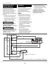
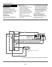
Precautions must be taken to prevent
electrical back feeding into utility
systems. This requires isolation of the
electrical system. To isolate the electrical
system, perform the following
procedures:
1. Turn off the main electrical system
switch prior to connecting the
generator.
2. In accordance with national and local
standards, a double throw transfer
switch must be installed in the
system.
Always shut off
main power prior
to temporary connection of the
generator to a building electrical
system.
Installation of the
generator as a
backup electrical source must be
performed by a qualified (licensed or
certified) electrical technician.
!
WARNING
!
WARNING
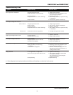
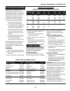
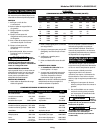
2.5 300 600 1000 600 375 250
5 600 1200 500 300 200 125
7.5 900 1800 350 200 125 100
10 1200 2400 250 150 100 50
15 1800 3600 150 100 65
20 2400 4800 175 125 75 50
25 3000 6000 150 100 60
30 3600 7200 125 65
40 4800 9600 90
Amps Watts Watts #8 #10 #12 #14 #16
120 V 240 V Wire Wire Wire Wire Wire
EXTENSION CORDS
MAXIMUM RECOMMENDED LENGTHS (IN FEET)
Operation (Continued)
www.campbellhausfeld.com
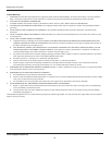
Air conditioner 2000-3000
Automatic washer 150-1500
Brooder 100+
Clothes dryer 5000-10,000
Coffee maker 400-700
Electric drill (small) 225-1000
Electric drill (large) 500-1000
Fan 40-200
Freezer 300-500
Hot plate 330-1100
Iron 500-1500
Light bulb As Rated
Load Device Watts Load Device Watts
Radio 50-200
Refrigerator 190-2000
Skillet 1200
Space heater 600-4800
Sump pump 400-3000
Television 200-500
Toaster 900-1700
Vacuum cleaner 200-300
Water pump 1000-3000
Water heater 1000-5000
Small hand saw 1000-2000
Large hand saw 1500-2500
ESTIMATED POWER USAGE (WATTS)
Installation for
Stand-by Use


