


2009 Inground Spas
LTR20091002, Rev. A
Preparing for Your New Inground Spa
www.calspas.com
13
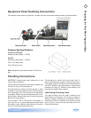
Connecting Plumbing to Remote
Equipment
Connecting the plumbing from the spa to the equip-
ment pack must be performed in accordance to local
and city codes.
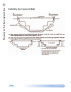
NOTE: Most codes require plumbing to be rigid PVC
schedule 40 or heavier in both above and below
ground installations. In most cases, the use of exible
PVC plumbing is acceptable when properly buried in
trenches.
Most water plumbing lines are 2” or larger and must
be schedule 40 or heavier PVC. When plumbing, mini-
mize the use of 90˚ elbows as much as possible. The
use of 45 ˚ elbows will increase the amount of jet
pressure you will have over the use of 90˚ elbows.
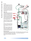
The plumbing on the spa shell is labeled by the factory
in the following manner:
Pump 1 Suction: 2” line that connects the spa lter
and bottom drain assembly to the front of pump 1.
Pump 1 Return: 2” line that connects the top of pump
1, through the equipment lter and heater back to
selected jets in the spa.
Pump 2 Suction: 2” line that connects the spa lter
and bottom drain assembly to the front of pump 2.
Pump 2 Return: 2” line that connects the top of pump
2 back to selected jets in the spa.
Ozone Line: 1” line that connects to a 1” exible line
extending off the bottom of the equipment pack lter
canister through an ozone injector (If ozone equipped)
and connected to ozone port on the spa.
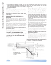
Air Blower: 1 1/2” line that is plumbed out of the air
blower (located on the equipment pack) and extended
up 18” above the spas water level to prevent water
ooding the air blower.
Air Venturi: 1/2” line that is plumbed 18” above the
spa’s water level.
Topside Control Panel and Temp Sensor: 1” line that
connects to the bottom of the control box located on
the equipment pack.
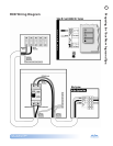
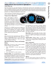
Electrical and Electronic Con-
nection
Remote Equipment Topside Control
Panel
The next few steps to complete the installation should
be performed along with installation of the tempera-
ture sensor and 12V spa light wiring (if applicable). All
of these components are generally installed using the
same conduit.
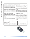
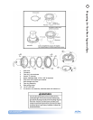
Locate the topside control panel extension loom 1.
in the control box mounted with the equipment
pack. This extension loom and attached black ter-
minal connector (see gure at right) will be used
to connect the topside control panel to the control
box.
Connect one end of the black terminal connector 2.
to the topside control panel cable.
Connect the other end of the terminal connector 3.
to the extension loom.
NOTE: This connection must be kept dry. We recom-
mend that a waterproof junction box be used in instal-
lations where moisture could penetrate this terminal
connector.
Lay out the extension loom to verify that you have 4.
enough length to reach the control box. Remem-
ber that conduit runs are not generally run in a
straight line. Every bend, and up and down run
consumes line length. Take this into consideration
when verifying electrical and plumbing runs.
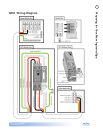
Connect the extension loom to the control panel 5.
location on the circuit board located inside the
control box. You will also need to connect both
the temperature and high limit sensors to the cir-
cuit board prior to testing. (See the temperature
and high limit installation instruction on the next
page for proper identication and see the wiring
diagram on the inside cover of the control box for
proper placement.)
Turn on the power supply to the spa equipment 6.
and briey test all functions on the topside control
panel to verify that both connections and exten-
sion loom are in working order before proceeding
with the installation.
NOTE: Circuit board programming will not allow spa
operation without both the temperature and high
limit sensors being properly connected to the circuit
board.