


SECTION IV
ASSEMBLY
22
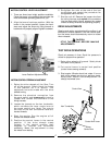
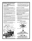
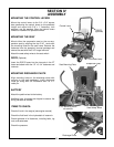
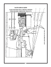
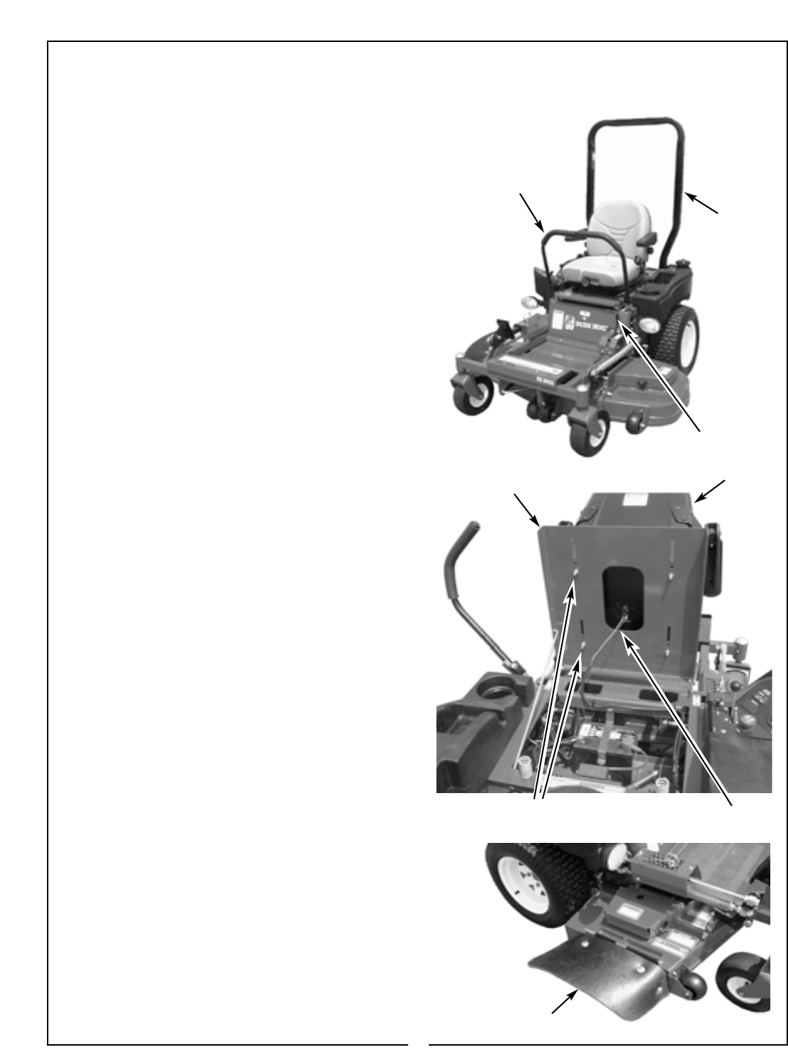
MOUNTING THE CONTROL LEVERS
Mount the control levers to the 3/4’ x 3/4” square
bars positioning the control levers to the preferred
height and mount with 3/8” x 1” fasteners, lock
washers, and flat washers. Move the control levers
forward or rearward for operator comfort.
MOUNTING THE SEAT
Mount either the suspension seat or the non-sus-
pension seat by aligning the four 5/16” studs with
the mounting holes on the seat frame. Remove the
fasteners from the operator’s manual package and
secure the seat with the 5/16” flange locknuts.
Attach the seat safety wires to the seat switch.
ROPS (Optional)
Insert the ROPS frame into the channels in the ZT
frame and attach with the 1/2” x 3-1/4” fasteners and
locknuts.
MOUNTING DISCHARGE CHUTE
Align mounting holes on the discharge chute with
mounts on the deck weldment. Insert discharge
chute pin along with 3/8” flatwasher and 1/8” x 1”
cotter pin.
BATTERY
Attach the positive lead to the battery.
Additional wire tie straps are shipped to secure the
wiring harness as needed.
ITEMS TO CHECK:
Check oil level in the engine (see engine manual)
Check the fluid level in the hydrostatic oil reservoir.
Check tightness of all fasteners, including bolts, lug
nuts, and setscrews.
Check tire pressure.
Suspension Seat
5/16” Mounting Studs
w/Locknuts
Discharge Chute
Seat Safety Wires
Control Lever
ROPS
(Optional)
Park Brake Lever
Seat Mounting Plate