


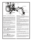

PTO PUMP & RESERVOIR KIT INSTALLATION
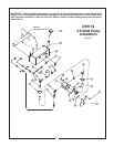
General Description CBH70
4.5 GPM Pump
The PTO Pump Kit consists of those parts required
to power the backhoe from the tractor’s PTO shaft. It
includes the PTO pump and adapter, reservoir, filtra-
tion system, hydraulic hoses, and fittings. In addi-
tion, it includes a pump plate which attaches to the
tractor’s drawbar and keeps the pump from turning
with the PTO shaft.
NOTE: The speed of the backhoe operation increas-
es as PTO speed increases.
Assembly
IMPORTANT - When installing hoses and fittings
always use thread sealant in permanent connec-
tions. Do not use thread sealant in union ends of
adapters. Do not over tighten fittings - they can
split or expand, causing leakage.
IMPORTANT - Have a suitable hoist available
before proceeding with loader setup.
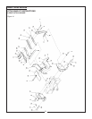
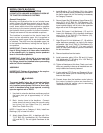
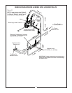
1. Assemble Filler Tube (27) and Breather Cap with
Dipstick (28) to Reservoir Tank (20).
2. Assemble Reservoir Tank (20) to backhoe main-
frame using 5/16” NF Locknuts (3).
3. Preassembly of Filter Base and Element (22):
Remove Filter Element from base to ease installa-
tion. Assemble Pipe Nipple (5) to “Inlet” port on filter
base (22).
Assemble 90 Degree Adapter Union (13) to “Outlet”
port on filter base (22).
4. Assemble Filter Base (22) to Reservoir Tank (20)
using 90 Degree Pipe Elbow (7) and 45 Degree Pipe
Elbow (6).
NOTE - Change Filter Element (29) every time oil is
changed.
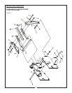
5. Assemble Suction Hose (12) to straight Barbed
Fitting (17) using Hose Clamp (18). Connect assem-
bly to 90 Degree Adapter Union (13) installed earlier
on the Filter Base and Element (22).
6. Install 90 Degree Adapter Union (25) top upper
port on Reservoir Tank (20). Install 90 Degree
Adapter Union (24) to Return Line “Check Valve” in
upper steel oil line located under Left Hand Foot Pad
area of the backhoe mainframe. Complete return
line connection to Reservoir Tank using Steel Oil
Line (23).
7. Reinstall Filter Element to the Filter Base.
8. Assemble Pump Plate (26) to Pump (11) using
two 3/8” NF x 1-3/4” Bolts (1), Lockwashers (8), and
Nuts (4). Pump Plate may have to be readjusted
later when installed on tractor PTO Shaft. The Plate
may need to be turned 180 degrees to provide prop-
er engagement with tractor drawbar and have ade-
quate clearances.
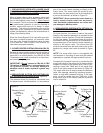
9. Slide PTO Adapter (19) onto pump shaft, allowing
1/8” clearance between Adapter (19) in place using
two Setscrews (9) and 5/16” NC Nuts (2).
10. Assemble Suction Hose (12) to Pump (11) using
Reducer Fitting (15) and 90 Degree Barbed Fitting
(16) Secure Hose using Hose Clamp.
11. Connect 36” Hydraulic Hose (21) to Inlet Line
steel oil line located under Left Hand Foot Pad area
of the backhoe mainframe. Complete connection to
Pump using 90 Adapter Union (14).
IMPORTANT - If hoses are connected incorrectly,
serious damage to the backhoe valve will result.
12. NOTE: Initial fill up of Reservoir Tank will require
4-1/2 gallons of fluid. Fill Reservoir with recommend-
ed fluid to correct level; refer to Service Section in
the Backhoe Manual.
13. Install the backhoe to the tractor at this time fol-
lowing the installation procedure in the Attaching
Section of the manual.
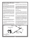
14. Slide complete Pump assembly onto the PTO
shaft of the tractor, making sure locking collar on
PTO Adapter has locked into position.
IMPORTANT - Make sure kinks DO NOT develop
in any of the lines. Suction hose can be short-
ened to prevent this problem.
!!
CAUTION
DO NOT REMOVE THE TRACTOR PTO SHIELD!
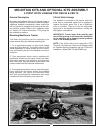
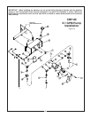
15. Pump Plate (26) may be adjusted (turned front to
back or bottom to top) on Pump (11) for proper fit-up
to tractor drawbar or three point mount if necessary.
The optimum position is to have the plate pointing
down and over the drawbar with the offset towards
the tractor. Refer to illustration.
An alternate position for the Pump Plate may have it
pointed upwards and retained by the Upper Bar of
the Three Point Mount Kit. Whatever position is
selected, it is important that the pump be restrained
from rotating. Refer to illustration.
36