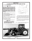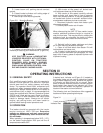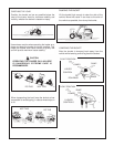
USE CAUTION WHEN MOUNTING
LOADERS EQUIPPED WITH OPTIONAL
CONTROL VALVE ON TRACTORS
EQUIPPED WITH CANOPY. RAISING
LOADER SUBFRAME TOO HIGH CAN
PINCH HAND BETWEEN CONTROL
HANDLE AND CANOPY CAUSING
INJURY.
WARNING
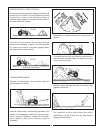
D. With tractor at idle speed, carefully activate
boom cylinders to raise/lower cross tube until it
aligns with front bracket channel.
E. Drive tractor forward until cross tube fully
engages front bracket channel and install front
bracket pin. (Figure 2-3)
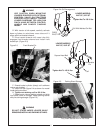
Figure 2-3 Front Bracket Pin
F. Extend bucket cylinder (dump) until subframe
rest on rear bracket.
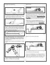
G. Install cuff per Figure 2-4 as shown for model
loader being mounted.
H. Tighten nut retaining cuff to 100 ft./lbs.
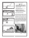
I. Raise boom, remove parking stands and slide
into loader frame for storage. Retain parking stands
with pins during storage. (Figure 2-5)
Figure 2-4 Cuff Arrangement
Figure 2-5 Parking Stand Storage
Fully Insert Stands And Pin Into Place
11
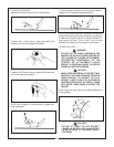
WARNING
DO NOT STAND UNDER LOADER WHILE
REMOVING/INSTALLING PARKING STANDS.
Tighten Nut To 100 ft./lbs.
Tighten Nut To 100 ft./lbs.
FIXED
PIVOT PIN
Cuff With Welded-On Bolt
LOADER MODELS:
2427 QT, 3227 QT
Removable
Pin
Cuff
Square Head Bolt
LOADER MODELS
2447 QT, 2847 QT


