


50” & 60” Allied Snowblower
- 5 -
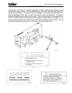
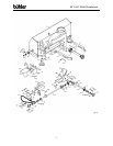
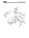
50" & 60" SNOWBLOWER ASSEMBLY INSTRUCTIONS
1. Mount the discharge spout (#2) using the spout clamp (#3) bolted to the spout
ring on the snowblower. Lubricate the spout ring and clamp. NOTE: A
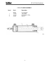
hydraulic cylinder and hose kit to control the spout deflector is available as an
option.
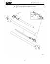
2. Hitch Assembly: With right and left hitch tubes (#5 & #6) turned as shown in
drawing, slide them into the sleeves welded to the main body. These tubes are
adjustable to four different positions. The correct position for each individual
tractor will be determined when mounting the snowblower on the tractor. These
tubes are connected to the snowblower with a 3/4" x 3 ¼” pin (#11) and a hairpin
clip (#12). Bolt the left (#84) and the right (#85) hitch arms to the outside of the
clevises on the hitch tubes using the lift pins (#9). NOTE: Pins should be turned
to the outside. Do not tighten any hardware until assembly is complete. Join the
top of the hitch arms by bolting a 1” O.D. x 2 ¼” spacer (#4) between the top
plates using a ¾” x 4” bolt and lock nut through the lower outside holes. Bolt the
hitch top bar (#86) between the same plates using the same bolt through the
welded tube on the bar. Use the inside holes on the top plates for the top bar.
The other end of the hitch top bar bolts to the top of the blower fan housing with a
½” x 1 ¾” hex bolt, lock washer and hex nut. Use the same hole position as the
hitch tubes. Tighten all hardware.
A category 1 top link pin (#8) is fitted in the top holes of the hitch arm plates.
This pin is used for standard three-point hitch only. The bushing in the lower
holes is used for the quick hitch.
3. Hand Crank Assembly: (Standard)
a) Bolt the crank mounting bracket (#16) to the top of the hitch using
3/8" x 1 ¼” hex bolts, lock washers and hex nuts.
b) Insert the crank tube (#15) through the mount and through the bracket
welded to the main housing. Lock the crank in place using a washer and
roll pin on each side of the bracket.
c) Thread the cable (#17) through the hole in the crank tube to even lengths
and wrap around the tube to each side of the hole four turns in opposite
directions.
d) With the spout turned forward, fasten the cable to the bracket welded to
the bottom of the spout using a ¼” cable clamp (#70).