


LT-200 Series
TP 300-4517-00-RG-N 3/200712
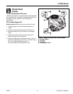
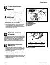
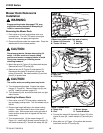
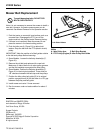
Gauge Wheels
The mower gauge wheels can be placed in several
positions depending on the height of cut. When using
higher cutting heights, set the wheels in the lower
position. When using lower cutting heights, set the
wheels in the upper position. To adjust:
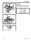
1. Remove the locknut (B, Figure 17), gauge wheel (C),
washer (D), and shoulder bolt (E). Change position of
gauge wheel to desired height.
2. Insert shoulder bolt (E) through washers (D) gauge
wheel (C), and gauge wheel bracket (A). Secure with
locknut (B). Repeat steps 1 & 2 for all gauge wheels.
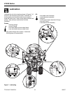
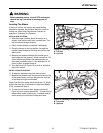
Seat Adjustment
Seat Slide Adjustment
The seat can be adjusted forward and back. Move the
lever (A, Figure 18), position the seat as desired, and
release the lever to lock the seat into position.
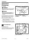
Adjustment
Procedures
Figure 18. Seat Adjustment
A. Seat Adjustment Lever
A
WARNING
Before checking mower, shut off PTO and engine,
remove the key, and allow all moving parts to
stop.
NOTICE
DO NOT remove the mower deck baffles. The
baffles help prevent grass clippings from
becoming airborne and plugging up the engine
cooling fins.
Figure 17. Fixed Bracket Gauge Wheel Adjustment
A. Gauge Wheel Bracket D. Washer
B. Locknut E. Shoulder Bolt
C. Gauge Wheel
A
B
C
E
D