


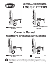
EMBLY INSTRUCTIONS
NOTE: The following instructions pertain to four SpeeCo log splitters, the 22 ton (LS401221), 25 ton (LS401216), 28 ton (LS401213)
and the 34 ton (LS401224). The four models share most of the component parts. Any differences are noted in the parts list and assembly
instructions.
NOTE: This log splitter was partially assembled at the factory. Refer to the drawing and parts list should it become necessary to disassemble the
unit for repair or replacement of parts.
STEP 1: Remove all the components from the crate. Inspect each piece for shipping damage. If any part is damaged, contact your dealer or
delivering carrier.
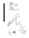
STEP 2: Attach the tongue (3) to the tank/axle (2) as shown in the diagram using the two 1/2 in. NC x 4-1/2 in. hex cap screws (48), 1/2 in.
lockwashers (47) and 1/2 in. NC hex nuts (46) from the hardware kit. Tighten. Make sure the ground stand (24) is in the vertical position.
NOTE: Flatwashers are included in the hardware kit should it be necessary to use them as spacers. This will eliminate play between the
tongue and the tank/tongue mounting plate.
STEP 3:
STEP 4: Stand the beam (1) up on end. NOTE: At least two people are required to raise the beam for the 28 ton and 34 ton models to insure
safety and prevent injury. Make sure that the beam is stable. Remove the pivot pin (52) and the clip pin (53) from the tank/axle (2). Roll
the axle/tongue assembly into position between the two tabs on the beam (1). Slide the pivot pin (52) through the holes and lock in place
with the clip pin (53).
STEP 5: Connect the end of the 1/2 in. I.D. x 44 in. (28 & 34 ton models) or 1/2 in. I.D. x 42 in. (22 & 25 ton models) hydraulic hose (21) coming
from the fitting (20) on the pump (9) to the fitting (75) on the valve (5) .
STEP 6: Slide one hose clamp (50) on the end of the 3/4 in. I.D. x 37 in. (28 ton and 34 ton models) or 3/4 in. I.D. x 32-1/2 in.
(22 & 25 ton models) hydraulic hose (49) that comes from the fitting on the tank/axle (2). Then connect the hose to the fitting (69) on the
valve (5). Tighten the hose clamp.
STEP 7: If the optional fender kit (standard on the 34 ton model) was purchased, attach the fenders (44) to the tank/axle (2) using the 1/4 in. NC
x 3/4 in. hex cap screws (43), 1/4 in. flatwashers (42), 1/4 in. lockwashers (41) and 1/4 in. hex nuts (40). Tighten.
IMPORTANT: The engine and hydraulic tank are shipped without oil. See the engine operating and maintenance instructions manual packed with
your log splitter for the type of crankcase oil, fuel, etc. The engine manufacturer recommends lead-free gasoline only.
Page 7
ASSEMBLY INSTRUCTIONS
Remove the rubber covering from the two spindles on the tank/axle (2). The wheel bearing cups, bearing cones, grease seals and
hub caps are already assembled. Bearing cones have been greased at the factory. Remove the blue, plastic protective covering from
the wheel hubs. Mount the wheels (54) to the spindles on the tank/axle (2) using the 3/4 in. light flatwasher (59) and 3/4 in. slotted nut (60)
from the hardware kit. There are two types of light flatwashers (59). Use the ones that best allow the wheel to rotate freely after the 3/4 in.
slotted nut (60) is tightened down and bearing play is removed. Install the cotter pin (61) and the hub cap (62) from the hardware kit.
Repeat step 4 for the other wheel.
OPERATING INSTRUCTIONS
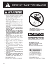
WARNING: Read and thoroughly understand all instructions and safety information before operating this
log splitter. Failure to do so may cause serious injury or death. Do not allow anyone to operate this log
splitter who has not read this manual. As with all power equipment a log splitter can be dangerous if it
is assembled or used improperly. Do not operate this log splitter if you have doubts or questions concerning
safe operation. Call our customer service department at 1-800-525-8322 to address these concerns.
Si no entiende ingles, se prefiere que busque alguien que interprete las instrucciones para usted.
CAUTION: DO NOT START OR RUN THE ENGINE WITHOUT OIL IN THE HYDRAULIC RESERVOIR AND ENGINE.