


STEP 1: Remove the top board from the crate.
Leave the side board facing the tank and wheels in
place. Remove the two end boards and the front
board.
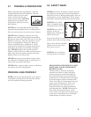
CAUTION: FLATTEN EXPOSED NAILS
WITH A HAMMER TO AVOID
POSSIBLE INJURY.
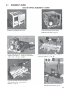
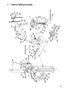
STEP 2: Remove the tongue assembly (3)* from
the crate. Put the ground stand (34)* in the
upright position and lock in place with pin (37)*.
STEP 3: Set one of the wood blocks from the
crate underneath the tank (2)* so that it sits in
the upright position.
STEP 4: Attach the tongue (3)* to the tank/axle
assembly (2)* as shown in the diagram using the
two
1
/2" NC x 4
1
/2" hex cap screws (27)*,
lockwashers (28)* and
1
/2" NC hex nuts (30)*
provided in the hardware kit. Flatwashers are
included in the hardware kit should it be
necessary to use them as spacers to eliminate play
between the tongue and tank/tongue mounting
plate. Tighten. The side board on the crate keeps
the unit stable. Remove the board after this
assembly step is complete.
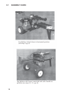
STEP 5: Roll the tank/tongue assembly (2 & 3)*
off the bottom board of the crate.
STEP 6: Remove the stripper plate (71)* from
the beam (1)* and set it aside. Turn the beam
assembly (1)* 90º and center it on the bottom of
the crate. Then slide the cylinder (4)* back as far
as possible from the beam foot plate until it locks.
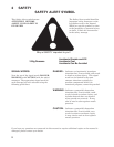
3 ASSEMBLY INSTRUCTIONS
8
NOTE:
The following instructions pertain to Gearmore Log Splitters, models T22B & T22H.
This Log Splitter comes partially assembled. Refer to the drawing and parts list should it become
necessary to disassemble the unit for repair or replacement of parts.
STEP 7: Attach the stripper plate (71)* to the
beam. You may need to wiggle the plate back and
forth until the holes line up. Use the
3
/8" bolts and
3
/8" lockwashers provided in the hardware kit.
Place the
3
/8" flatwashers provided in the
hardware kit in front of the lockwashers next to
the hole. Push the stripper plate (71)* down until
there is no play in the bolts. Tighten.
STEP 8: Slide the beam (1)* off the bottom of
the crate and carefully set it upright. Roll the
tank/tongue assembly (2 & 3)* into position
between the two tabs on the beam (1)* as shown
in the diagram. Slide the pivot pin (25)* through
the holes and secure with clip pin (26)*.
STEP 9: Lower the beam (1)* to the horizontal
position so that the hole in the beam fits over the
pin (32)* on the tongue (3)*. Lock in place with the
lynch pin (31)* provided in the hardware kit.
STEP 10: Connect the
3
/4" I.D. x 35" return hose
(53)* to the
3
/4" NPT x
3
/4" tube fitting on the valve
(5)*. Tighten hose clamp (18)*. Remove the plastic
plug from the other valve port and connect the
1
/2"
I.D. pressure hose coming from the pump (9)* to
the swivel elbow fitting (50)* on the valve (5)*.
Tighten the nut securely.
STEP 11: Remove the pin and cotter from the
valve (5)* handle. Put the handle in the upright
position and secure with pin and cotter.
* See Parts Breakdown (Pages 15 - 17) in this manual.