


16
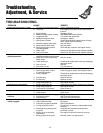
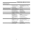
Troubleshooting, Adjustment, & Service
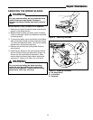
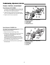
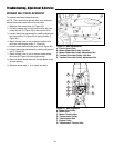
TRAVEL CONTROL ADJUSTMENT
Serial Number 0-011903999
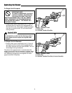
1. The Travel Control engagement bars (A, Figure 16a)
should be an equal distance from the Upper Handle
Bar. If they are not, adjust their position.
2. Loosen the wing nut locknut (D) and rotate control
rod (C) until engagement bars are properly adjusted.
3. Tighten locknut to secure adjustment.
A
B
A
C
D
Figure 16a - Travel Controls Adjustment
A. Engagement Bars
B. Upper Handle
C. Control Rod
D. Wing Nut Locknut
A
B
C
D
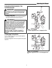
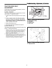
Figure 16b - Travel Controls Adjustment
A. Engagement Bars
B. Hair Pin Clip
C. Control Rod
D. Jam Nut
Serial Number 012003001-Up
The Travel Control engagement bars (A, Figure 16b) can
be adjusted to provide the optimum ratio of
forward/reverse travel speed.
1. Remove the hair pin clip (B, Figure 16b).
2. Relocate the L-shaped end of the control rod (C) into
one of the four speed adjustment holes in the
engagement bar side plate.
The rearmost hole will provide the most forward
speed and the least reverse speed, and vice-versa.
Finer adjustment can be obtained by loosening the
jam nut (D) and turning the rod in or out.
3. Secure the in the desired position by replacing the
hair pin clip (B).