6
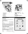
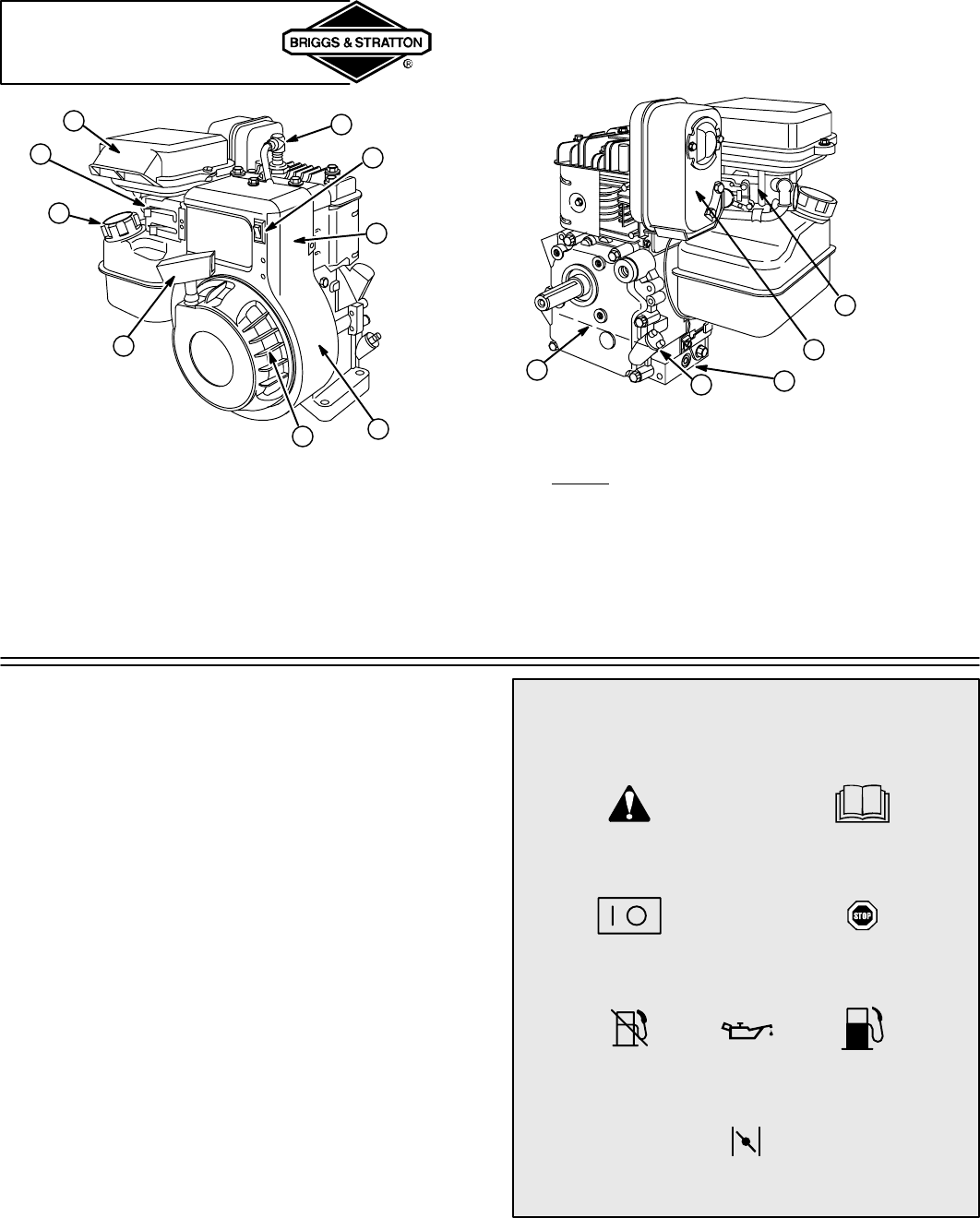
ENGINE PARTS
1. Blower housing
2. Finger guard/
Rotating screen
3. Rope handle
4. Fuel fill
5. Control levers
6. Air cleaner
7. Spark plug wire
8. Stop switch (if equipped)
9. Engine Model Type Code
xxxxx xxxx xx xxxxxxxx
10. Oil level
11. Oil fill cap
12. Oil drain plug
13. Muffler/(Muffler guard, if equipped)/
(Spark arrester, if equipped)
14. Carburetor
4
5
3
7
6
8
1
2
9
12
13
10
11
14
GENERAL INFORMATION
ENGINE MODEL
This is a single cylinder, L-head, air-cooled engine. It is a
low emissions engine.
MODEL SERIES 90000
Bore 2-9/16 in. (65.09 mm). . . . . . . . . . . . . . . . . . . . . . . . . .
Stroke 1-3/4 in. (44.45 mm). . . . . . . . . . . . . . . . . . . . . . . . .
Displacement 9.02 cu. in. (148.0 cc). . . . . . . . . . . . . . . . . .
Note: For practical operation, the horsepower loading should
not exceed 85% of rated horsepower. Engine power will de-
crease 3-1/2% for each 1,000 feet (300 meters) above sea
level and 1% for each 10° F (5.6° C) above 77° F (25° C).
Engine will operate satisfactorily at an angle up to 15°.
TUNE-UP SPECIFICATIONS
Armature air gap 0.006 – 0.010 in. (0.15 – 0.25 mm). . .
Spark plug gap 0.030 in. (0.76 mm). . . . . . . . . . . . . . . . . .
Valve clearance with valve springs installed and piston 1/4 in.
(6 mm) past top dead center (check when engine is cold).
See Repair Manual P/N 270962.
Intake 0.005 – 0.007 in. (0.13 – 0.18 mm). . . . . . . . . . . . .
Exhaust 0.007 – 0.009 in. (0.18 – 0.23 mm). . . . . . . . . . .
THE INTERNATIONAL SYMBOLS USED
ON THE ENGINE OR
IN THIS MANUAL INCLUDE:
On Off
Fuel Shutoff
Read Owner’s
Manual
Stop
Fuel
Choke
Safety Alert
Oil


