


44
www.ferrisindustries.com
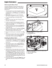
Installing the Operator Compartment
Assembly
1. Park the machine on a flat, level surface such as
a concrete floor. Disengage the PTO, engage the
parking brake, turn off the engine, and remove the
ignition key.
2. Place the operator compartment assembly (C,
Figure 62) on the unit and loosely install the two
(2) 1/2” bolts and washers (A & B) through the
spacers (D) in the rubber pivot mounts (E) and into
operator compartment front pivots.
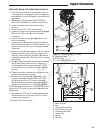
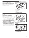
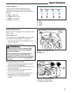
3. Install the shock (B, Figure 63) to the bottom
shock mount (C) and secure in place using the 3/8
X 2-1/2” bolt, 3/8 washer and 3/8-16 nylock flange
nut (A).
4. Install the eyebolt (C, Figure 60) to the ground
speed control lever arm (A) and secure using the
eyebolt hardware (B). The eyebolt should be on
the inside edge of the ground speed control lever
arm tab and the hardware should be routed so it
faces towards the center of the unit.
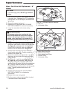
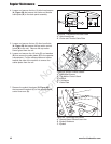
5. Install the cable plates (E, Figure 59) to the
operator compartment and secure using the four
(4) 1/4 bolts (C) and washers (D).
6. Install the top motion control guard (B) onto the
unit and secure in place using the two (2) allen
head bolts (A).
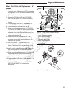
7. Connect the wire harness by pushing the
instrument panel wire harness connector (A,
Figure 61) into the main unit wire harness
connector (B).
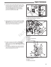
8. Install the choke and throttle cable plate (B,
Figure 58) into the instrument panel and secure
using the four (4) allen head screws (A).
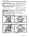
9. Position the left fuel tank (A, Figure 56) onto the
machine and secure in place using the three (3)
bolts, lock washers and washers (B).
10. Install the right tank (A, Figure 57) on the machine
and secure in place using the three (3) wing bolts
(B).
Regular Maintenance
Not for
Reproduction