


38 www.ferrisindustries.com
Troubleshooting
Troubleshooting, Adjustment & Service
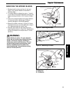
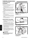
2" - 2-1/8"
(5,0 - 5,4cm)
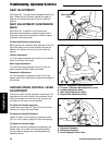
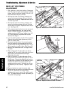
Figure 31. Parking Brake Adjustment
A. Upper Brake Spring
A
PARKING BRAKE ADJUSTMENT
1. Disengage the PTO, stop the engine, block the
front wheels, remove the ignition key, and engage
the parking brake.
2. Locate the upper brake spring (A, Figure 31).
3. With the parking brake engaged, measure the
compressed spring length. The spring should be
2” to 2-1/8” (5,0 - 5,4 cm) when compressed.
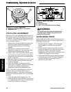
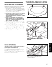
4. If the spring is not within this range, jack up the
rear of the machine and secure with jackstands.
Remove both drive tires.
5. Locate the lower brake spring and adjustment
clevis (A & B, Figure 32).
6. Release the parking brake and disconnect the
clevis (B) from the caliper lever (C). Turn the
clevis to compress or release the upper spring.
Lock the nut against the clevis and reinstall the
clevis onto the caliper lever.
CAUTION
Do not adjust the spring to be shorter than
2” (5,0 cm) when compressed. This may
damage the brake caliper.
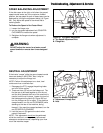
Figure 32. Parking Brake Adjustment
A. Lower Brake Spring
B. Adjustment Clevis
C. Caliper Lever
A
B
C
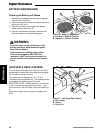
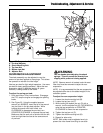
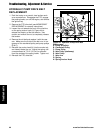
Figure 30. Neutral Return Adjustment
A. Ball Joint
B. Jam Nut
C. Neutral Return Rod
C
A
B
RETURN-TO-NEUTRAL
ADJUSTMENT
To determine if it is necessary to adjust the neutral
return, perform the following steps.
1. Disengage the PTO, engage the parking brake
and turn off the engine.
2. Move the ground speed control levers into the
operating position, pull levers rearward and
release.
3. Move the ground speed control levers towards the
neutral position. If the levers do not align with the
notches in the neutral lock plate, it is necessary to
adjust the neutral return rod (C, Figure 30).
Adjustment
1. Loosen the jam nut (B) locked against the ball
joint (A).
2. Turn the neutral return rod (C) to adjust handle
position (see Figure 30).
3. Pull lever rearward and release to check position
again. Adjust as necessary to align levers with
notches.
4. Once the lever alignment has been adjusted, lock
jam nut against the ball joint.