


43
Troubleshooting, Adjustment & Service
B
C
A
B
B
B
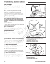
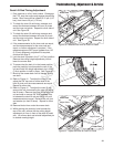
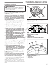
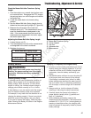
Figure 46. PTO Clutch Adjustment
A. Adjustment Window (Qty. 3, one shown)
B. Adjustment Nut
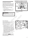
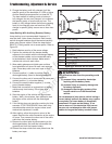
Figure 47. Adjust PTO Clutch
A. Window
B. Adjustment Nut
C. .016”-.018” (0,40-0,45mm) Feeler Gauge
PTO Clutch Adjustment
All other Models: S/N: All
Briggs & Stratton 543777-0120-E1 Models: S/N:
2013556397 & Above:
Check the PTO clutch adjustment after the initial 25
hour break-in period and then after every 100 hours
of operation. Also perform the following procedure
if the clutch is slipping or will not engage, or if a new
clutch has been installed.
1. Remove key from ignition switch and disconnect
spark plug wires to prevent the possibility of
accidental starting while the PTO is being
adjusted.
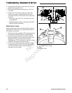
2. See Figure 46. Note the position of the 3
adjustment windows (A) in the side of the brake
plate and the nylock adjustment nuts (B).
3. Insert a .016”-.018” (0,40-0,45mm) feeler gauge
(C) through each window, positioning the gauge
between the rotor face and the armature face as
shown in Figure 47.
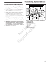
4. Alternately tighten the adjustment nuts (B, Figure
47) until the rotor face and armature face just
contacts the gauge.
5. Check the windows for an equal amount of drag
when the gauge is inserted and removed, and
make any necessary adjustments by tightening or
loosening the adjustment nuts.
NOTE: The actual air gap between the rotor and
armature may vary even after performing the
adjustment procedure. This is due to dimensional
variations on component parts, and is an acceptable
condition.
6. Check the mower blade stopping time. See
BLADE BRAKE CHECK. The mower blades and
mower drive belt should come to a complete stop
within seven (7) seconds after the electric PTO
switch is turned off.
Briggs & Stratton 543777-0120-E1 Models: S/N:
2013556397 & Above:
If the clutch is slipping or the clutch will not engage,
the air gap can be adjusted by removing the re-gap
shim to allow the clutch to continue to function.
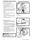
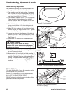
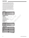
1.
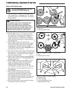
Loosen both brake mounting bolts (A, Figure 48)
1/2 to 1 full turn as shown in Figure 48.
IMPORTANT NOTE: Do not remove the brake pole
(B, Figure 48) from the clutch. The brake pole must
remain in the correct position to ensure proper brake
torque.
WARNING
To avoid serious injury, perform adjustments
only with engine stopped, key removed and
tractor on level ground.
A
A
C
B
Figure 48. PTO Clutch Adjustment
A. Brake Mounting Bolts
B. Brake Pole
C. Re-gap Shim
Not for
Reproduction