


Mower Removal and Installation
NOTE: Perform mower installation and removal on a hard
flat surface such as a concrete floor.
Removal
1. Disengage the PTO, engage the parking brake, lock
the ground speed levers into their START/PARK posi-
tions, turn off the ignition, remove the key, and wait
for all moving parts to stop.
2. Place a 2 x 4 or similiar support under each end of
the mower deck, then lower the mower deck to its
lowest position. See Cutting Height Adjustment.
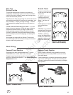
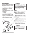
3. Pull back on the tensioning idler (F, Figure 18) in
the direction indicated by the arrow, and remove the
mower belt from the PTO pulley (C).
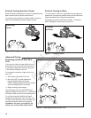
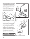
4. Remove the hairpin clips and washers (A, Figure 19)
securing the rear mower deck brackets (B) to the rear
lift arms (C), and pull the arms out from the holes in
the brackets. Retain all removed hardware.
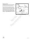
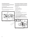
5. Remove the hairpin clips and washers (A, Figure 20)
securing the front mower deck bracket (B) to the front
lift rods (C), and pull the rods out from the holes in the
bracket. Retain all removed hardware.
6. Pivot the front wheels out of the way and slide the
mower deck out from under the unit.
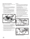
Figure 18. Mower Belt Routing
A
C
D
E
E
E
D
F
B
Figure 19. Rear Deck Lift Components
(Right side shown, left side same)
Installation
1. Disengage the PTO, engage the parking brake, lock
the ground speed levers into their START/PARK posi-
tions, turn off the ignition, remove the key, and wait
for all moving parts to stop.
2. Lower the mower deck to its lowest position (see
Cutting Height Adjustment).
3. Pivot the front wheels out of the way and slide the
mower deck under the unit. Place a 2 x 4 or similar
support under each end of the mower deck.
4. Insert the front lift rods (C, Figure 20) into the bottom
holes in the front mower deck bracket (B), and secure
each with a washer and hairpin clip (A).
5. Insert the rear lift arms (C, Figure 19) into the front
holes in the rear mower deck brackets (B), and
secure each with a washer and hairpin clip (A).
6. Pull back on the tensioning idler (D, Figure 18) in the
direction indicated, and install the belt onto the PTO
pulley as shown in Figure 18.
Important: Be sure the belt is installed properly onto
all pulleys.
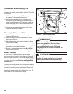
Figure 20. Front Deck Lift Components
(Right side shown, left side same)
C
B
A
C
A
B
25
en
Not for
Reproduction