


4
Installation Instructions Sub-Frame Hitch
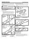
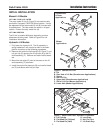
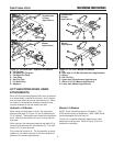
Figure 2. Install Support Clamp
A. 5/16-18 x 1 Carriage Bolt D. 11/32 Washer
B. Hook Assembly E. 5/16 Lockwasher
C. Support Clamp F. 5/16-18 Nut
B
C
D
E
A
F
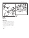
Figure 4. Assemble Lift Rod
A. Lift Rod C. Spring
B. Set Collar D. Rod Guide
B
C
D
B
A
NOTE: Please read through these instructions and the
instructions of any other attachments before beginning
installation.
INITIAL ASSEMBLY
Assemble Hitch
1. Attach the support clamp (C, Figure 2) and hook
assembly (B) to the hitch. Secure with four 5/16-18 x
1 carriage bolts (A), washers (D), lockwashers (E),
and nuts (F). Do not tighten the hardware at this
time.
WARNING
Before beginning any service work turn off the
PTO, set the parking brake, turn off the ignition,
and disconnect the spark plug wire(s).
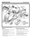
Figure 5. Early/Later Lift Links
A. Early Model Lift Link
B. Later Model Lift Link
A
B
Conquest / 1700 /
2700 &
Prestige / 1800 /
2800 Series
B
C
D
E
A
F
Broadmoor /
1600 / 2600
Series
Assemble Push Bar Latch
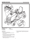
1. Attach Push Bar Latch (B, Figure 3), to hitch. Secure
with four .31-16 x 1 bolts (A), and four .38-16 flange
nuts (C).
Two Wheel
Drive Models
Four Wheel
Drive Models
A
B
C
Figure 3. Assemble Push Bar Latch
A. Bolt, .38-16 x 1 C. Flange Nut, .38-16
B. Push Bar Latch
Assemble Lift Rod
1. Install the set collars (B, Figure 4), spring (C), and
rod guide (D) on the lift rod (A) as shown. Final
adjustment of the set collars will be made after the
hitch and attachment are installed.