


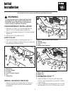


Normal Installation
& Removal
10
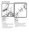
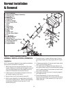
Figure 11. Normal Installation & Removal
A. Hitch Assembly
B. Bag and Cover Support Assembly
C. Shoulder Rest
D. Mount Pin
E. Retainer Spring
F. Hinge Pins
G. Retainer Springs
H. Cover hinge Pivots
I. Cover
J. Bag
K. Bag Hanger
L. Ridge Cutout
M. Upper Tube
N. Ridge
O. Middle Tube
P. Rubber Strap, Middle
Q. Pin
R. Lower Chute
S. Lower Chute Rod
T. Mounting Plate
U. Rubber Strap, Lower Chute
V. Discharge Deflector
W. Locknut Mount
X. Support Mount
G
F
A
Q
NORMAL INSTALLATION & REMOVAL
Installation
NOTE: See previous pages for more detailed installation
and operation instructions if necessary.
1. Attach bag and cover support assembly (B) to hitch
support assembly (A) by sliding the support mount (X)
over the upright support until the support mount (X)
makes full contact with the shoulder bolts (C).
2. Insert mount pin (D) through the support mount (X)
and upright support (A) as shown.
3. Secure mount pin (D) with retainer spring (E).
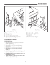
4. Attach cover assembly (I) to bag support bracket (B)
using cover hinge pivots (H). Secure cover assembly
to bag support bracket using hinge pins (F) and
retainer springs (E).
5. Raise the cover (I), attach collector bags (J) using
grass bag hanger (K) to bag hanger post (D, Figure
7).
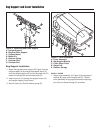
6. Lift discharge deflector (V) up and insert lower chute
rod (S) into mounting plate (T).
7. Pull rubber strap (U) below discharge deflector (U)
and secure lower chute (R) to mower deck by placing
hole in rubber strap (U) (hole closest to lower chute)
over locknut mount (W).
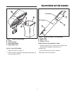
8. Slide upper tube (M) into cover (I) aligning ridge (N)
with ridge cutout (L).
9. Slide tube assembly (O) over lower chute (R)
securing tube assembly (O) to lower chute (R) using
rubber strap (P) on tube assembly (O) to pin (Q) on
lower chute (R).
L
M
E
I
C
D
N
O
P
R
S
T
U
W
V
B
C
F
G
H
J
K
X