


5
Sub-Frame Hitch Installation Instructions
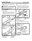
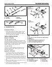
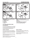
Figure 5. Assemble Lift Rod
A. Lift Rod C. Spring
B. Set Collar D. Rod Guide
B
C
D
B
A
Assemble Lift Rod
1. Install the set collars (B, Figure 4), spring (C), and
rod guide (D) on the lift rod (A) as shown. Final
adjustment of the set collars will be made after the
hitch and attachment are installed.
INITIAL INSTALLATION
Manual Lift Models
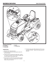
LIFT LINK - EARLY VS. LATER
The early model lift link (A, Figure 6) was used on early
production Conquest/1700/2700 Series tractors. It must
be replaced with the later model lift link (B) included with
this attachment. The later model link works in all appli-
cations. Discard the early model link (A).
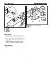
LIFT LINK POSITION
The lift link is installed differently depending on what
attachment is being used. Refer to Figure 7 for link
installation information.
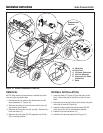
Hydraulic Lift Models
1. Fully lower the hydraulic lift. The lift assembly is
spring loaded so it will need to be held in the down
position to perform of the following procedures.
2. Remove and retain the flat head pin (B, Figure 8) and
hair pin clip (E) securing the lift cylinder (A) to the lift
shaft assembly (F). Remove and retain the flat wash-
ers.
3. Mount the lock plate (D) next to the cams on the lift
shaft assembly (F) as shown.
4. Install the original flat head pin (B) and new flat head
pin (C) and secure with hair pin clips.
A
B
C
D
E
A
F
C
D
G
Figure 7. Connect Lift Link
A. Pin
B. Rear Hole of Lift Bar (Snowthrower Applications)
C. Spacer
D. Hair Pin Clip
E. Upper Hole (Snowthrower Applications)
F. Slot of Lift Link (Mower Applications)
G. Lower Hole (Mower Applications)
Snowthrower
& Dozer
Applications
Mower
Applications
Figure 6. Early/Later Lift Links
A. Early Model Lift Link
B. Later Model Lift Link
A
B
Figure 8. Install Lock Plate - Hydraulic Lift Models
A. Lift Cylinder D. Lock Plate
B. Flat Head Pin (Original) E. Hair Pin Clips
C. Flat Head Pin (New) F. Lift Shaft Assy.
A
B
C
D
F
E