2-8
Installation Instructions Power Steering Conversion Kit
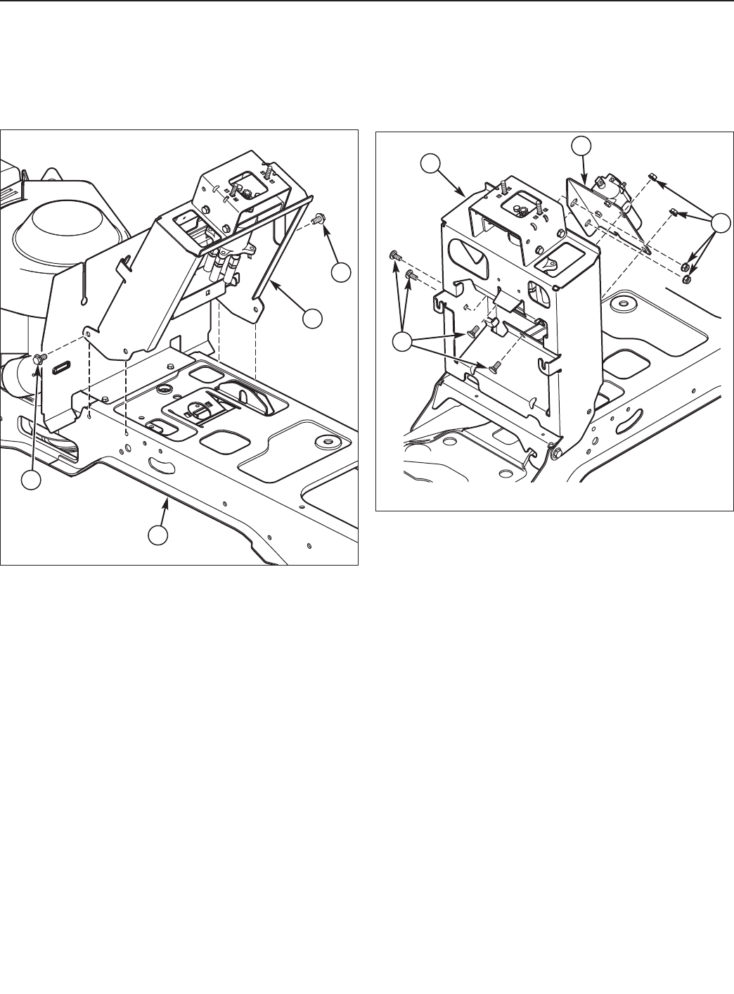
NOTE: For initial installation, only two screws are used
(as shown) and the screws are to be loosely installed to
allow the tower to pivot.
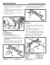
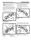
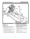
3. Attach new tower assembly (A, Figure 15) to frame
(A) using two 3/8-16 x 3/4 taptite screws (C).
A
B
C
C
Figure 15 Tower Assembly Installation
A. New Tower Assembly
B. Frame
C. Taptite Screws, 3/8-16 x 3/4
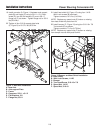
4. Install control valve spool and support (B, Figure 16)
to the new tower (A) using (previously removed) four
5/16-18 x 3/4 carriage bolts (C), and four 5/16-18
KEPS lock nuts (D).
Tighten lock nuts to 7 ft. lbs (9.75 Nm).
Figure 16 Control Valve Spool & Support Installation
A. New Tower Assembly
B. Control Valve Spool & Support
C. Carriage Bolts, 5/16-18 x 3/4
D. Lock Nuts, KEPS, 5/16-18
A
B
D
C


