


8
BRIGGSandSTRATTON.COM
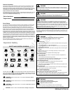
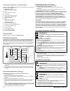
Maintenance Chart
First 5 Hours
Change oil
Every8HoursorDaily
Check engine oil level
Clean area around muffler and controls
Clean finger guard (if equipped)
Every 50 Hours or Annually
Clean air filter *
Clean pre-cleaner (if equipped) *
Change engine oil
Replace oil filter (if equipped)
Check muffler and spark arrester
Every 200 Hours or Annually
Replace air filter *
Replace pre-cleaner (if equipped) *
Annually
Replace spark plug
Clean air cooling system *
Clean/Replace fuel filter (if equipped)
Check valve clearance **
* Industy conditions or when airborne debris is present, clean more often.
** Not required unless engine performance problems are noted.
Carburetor Adjustment
Never make adjustments to the carburetor. The carburetor was set at the factory to
operate efficiently under most conditions. However, if adjustments are required, see a
Briggs & Stratton Authorized Dealer for service.
NOTICE: The manufacturer of the equipment on which this engine is installed specifies
the top speed at which the engine will be operated. Do not exceed this speed.
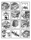
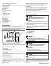
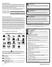
How To Replace The Spark Plug - Figure
7
Check the gap (A, Figure 7) with a wire gauge (B). If necessary, reset the gap. Install
and tightenthe sparkplug tothe recommended torque.For gapsetting ortorque, seethe
Specifications section.
Note: In some areas, local law requires using a resistor spark plug to suppress ignition
signals. If this engine was originally equipped with a resistor spark plug, use the same
type for replacement.
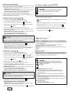
Inspect Muffler And Spark Arrester - Figure
8
Running engines produce heat. Engine parts, especially muffler,
become extremely hot.
Severe thermal burns can occur on contact.
Combustible debris, such as leaves, grass, brush, etc. can catch fire.
WARNING
Allow muffler, engine cylinder and fins to cool before touching.
Remove accumulated debris from muffler area and cylinder area.
It is a violation of California Public Resource Code, Section 4442, to use or
operate theengine onany forest-covered, brush-covered,or grass-covered land
unless the exhaust system is equipped with a spark arrester, as defined in
Section 4442, maintained in effective working order. Other states or federal
jurisdictions may have similar laws. Contact the original equipment
manufacturer, retailer, or dealer to obtain a spark arrester designed for the
exhaust system installed on this engine.
Remove accumulated debris from muffler area and cylinder area. Inspect the muffler (A,
Figure 8) for cracks, corrosion, or other damage. Remove the spark arrester (B), if
equipped, and inspect for damage or carbon blockage. If damage is found, install
replacement parts before operating.
WARNING: Replacement parts must be ofthe same design and installed
in the same position as the original parts. Other parts may not perform as well, may
damage the unit, and may result in injury.
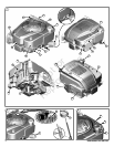
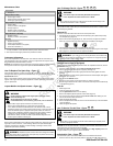
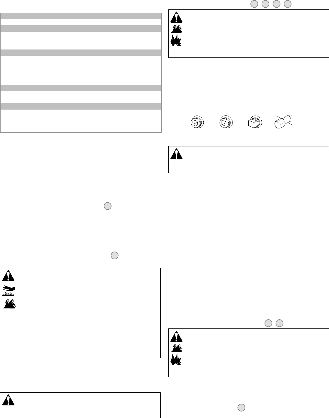
How To Change The Oil - Figure
2 9 10 11
WARNING
Fuel and its vapors are extremely flammable and explosive.
Fire or explosion can cause severe burns or death.
If you drain the oil from the top oil fill tube, the fuel tank must be empty or fuel
can leak out and result in a fire or explosion.
Used oil is a hazardous waste product and must be disposed of properly. Do not discard
with householdwaste. Check with your localauthorities, servicecenter, ordealer forsafe
disposal/ recycling facilities.
Remove Oil
Drain the oil from the bottom drain hole or from the top oil fill tube.
1. With engine off but still warm, disconnect the spark plug wire (A) and keep it away
from the spark plug (Figure 9).
2. Remove the oil drain plug (B, Figure 10). Drain the oil into an approved container.
Note: Any of the oil drain plugs shown below may be installed in the engine.
3. After the oil has drained, install and tighten the oil drain plug.
4. If you drain the oil from the top oil fill tube (C), keep the spark plug end of the engine
(D) up (Figure 11). Drain the oil into an approved container.
WARNING: If you drain the oil from the top oil fill tube, the fuel tank must
be empty or fuel can leak out andresult in a fire or explosion. To empty the fueltank,
run the engine until it stops from lack of fuel.
Change The Oil Filter (if equipped)
Some models are equipped with an optional oil filter. For replacement intervals, see the
Maintenance chart.
1. Drain the oil from the engine. See the How To Change The Oil section.
2. Remove the oil filter (E) and dispose of properly. See Figure 2.
3. Before you install the new oil filter, lightly lubricate the oil filter gasket with fresh,
clean oil.
4. Install the oil filter by hand until the gasket contacts the oil filter adapter, then tighten
theoilfilter1/2to3/4turns.
5. Add oil. See the Add Oil section.
6. Start and run the engine. As the engine warms up, check for oil leaks.
7. Stop the engine and check the oil level. It should be at the top of the full indicator (J)
on the dipstick (Figure 2).
Add Oil
Place engine level.
Clean the oil fill area of any debris.
See the Specifications section for oil capacity.
1. Remove the dipstick (G) and wipe with a clean cloth (Figure 2).
2. Pour the oil slowly into the engine oil fill (H). Do not overfill. After adding oil, wait
one minute and then check the oil level.
3. Install and tighten the dipstick.
4. Remove thedipstick andcheck the oillevel. Itshould be at thetop of the fullindicator
(J) on the dipstick.
5. Install and tighten the dipstick.
How To Service The Air Filter - Figure
12 13
WARNING
Fuel and its vapors are extremely flammable and explosive.
Fire or explosion can cause severe burns or death.
Never start or run the engine with the air cleaner assembly (if equipped) or the
air filter (if equipped) removed.
NOTICE: Do not use pressurized air or solvents to clean the filter. Pressurized air can
damage the filter and solvents will dissolve the filter.
Two types of air filter systems are shown, a Standard and a High Capacity. Determine
the type installed on your engine and service as follows.
Standard Air Filter - Figure
12
The air cleaner system uses a foam element that can be washed and reused.
1. Movetheslidelock(A) to the unlock position. Open the cover (B). See Figure 12.
Not for
Reproduction