


8. Cut two pin connector ends off of current transformer
leads and discard. Strip wires and place in supplied
wire connectors.
9. Using installer supplied 300VAC or greater wire, run
wires from wire connectors to control module terminal
block labeled “CT1A” through “CT2B” in power
management system.
10. Using installer supplied 300VAC or greater wire,
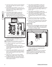
connect C (Common) and NO (Normally Open)
terminals on terminal strip J9 of control module in
transfer switch to control module terminal block labeled
“TXSF” and “TXFG” in power management system.
11. Wire the air conditioner thermostat control wiring to the
control module labeled “AC1A-AC2B” in power
management system.
NOTE: AC1A and AC1B is for the priority 1 air conditioner.
AC2A and AC2B is for the priority 2 air conditioner.
12. For 120VAC selected loads, remove wire from selected
load circuit breaker.
13. Using installer supplied 300VAC or greater wire,
connect selected load circuit breaker to terminal block
at power management system labeled “CB/B1” for
priority 1 load.
14. Using installer supplied 300VAC or greater wire and a
wire nut, connect the selected load wire to terminal
block in power management system labeled “RLY/B1”
for priority 1 load.
15. Repeat steps 12 through 14 for all other 120VAC
priorities using terminals “CB/C1” through “RLY/D2”.
16. For 240VAC selected loads, remove both wires from
selected load circuit breaker and place in load side of
installer supplied contactor.
17. Using installer supplied 300VAC or greater wire,
connect circuit breaker to line side of contactor.
18. Using installer supplied 300VAC or greater wire,
connect one pole of the circuit breaker to terminal block
in power management system labeled “CB/B1” for a
priority 1 load.
19. Using installer supplied 300VAC or greater wire,
connect Neutral in main breaker panel to contactor coil.
20. Using installer supplied 300VAC or greater wire,
connect contactor coil to terminal block in power
management system labeled “RLY/B1” for a priority 1
load.
21. Repeat steps 16 through 20 for all other 240VAC
priorities using terminals “CB/C1” through “RLY/D2”.
22. Tighten all wire connections/fasteners to proper torque.
See inside power management system enclosure for
proper torque values.
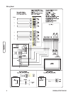
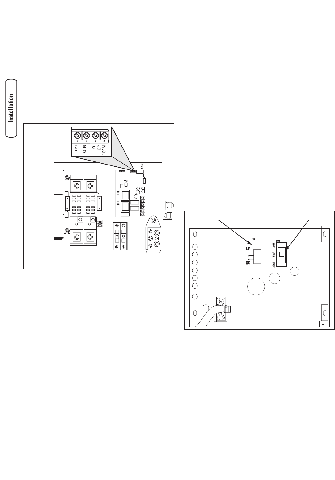
System Setup
You must perform the following before operating the system:
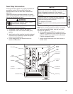
• Place the switch labeled “SW2” on the control module
in the NG or LP position, whichever is appropriate for
the installed home standby system.
• Place the switch labeled “SW3” on the control module
to match the rating of the home standby system.
• In main breaker panel, turn selected load circuit
breakers to the ON position.
IMPORTANT: After installation of the power management
system is complete, turn on utility power to the home
standby generator and transfer switch. Wait one minute
before turning generator to AUTO.
6 BRIGGSandSTRATTON.COM
SW3
SW2
Location of J9 Terminal Strip in Transfer Switch