


7
Briggs & Stratton Power Products Automatic Transfer Switch
Installation and Owner’s Manual
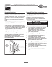
Mounting Guidelines
The Model 01917 Automatic Transfer Switch is enclosed in
a NEMA Type 1 enclosure suitable for indoor use only.
The Model 01918 Automatic Transfer Switch is enclosed in
a NEMA Type 3R enclosure suitable for indoor/outdoor
use.
Guidelines for mounting the Automatic Transfer Switch
include:
• Model 01918 Automatic Transfer Switch must be installed
with minimum NEMA 3R hardware for conduit
connections.
• Install the switch on a firm, sturdy supporting structure.
• To prevent switch contact distortion, level and plumb the
enclosure.This can be done by placing washers between
the switch enclosure and the mounting surface.
• NEVER install the switch where any corrosive substance
might drip onto the enclosure.
• Protect the switch at all times against excessive moisture,
dust, dirt, lint, construction grit and corrosive vapors.
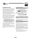
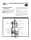
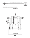
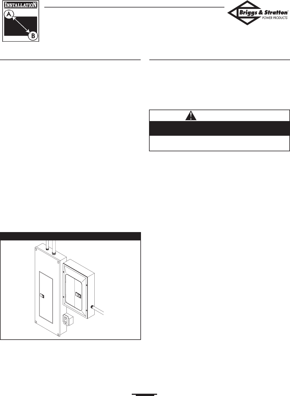
The typical installation of the Automatic Power Transfer
Switch is depicted in Figure 2. Discuss layout
suggestions/changes with the owner before beginning the
system installation process.
Power Wiring Interconnections
All wiring must be the proper size, properly supported, of
approved insulation qualities, and protected by NEC
approved conduit.
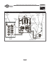
Complete the following connections between the
generator, transfer switch and main distribution panel
(Figure 3, on next page).
1. Connect utility power supply leads from a two pole
breaker installed in the main distribution panel to
transfer switch terminals marked “UTILITY
CONNECTION”. Use a 50 Amp circuit breaker.
Ensure breaker is turned OFF.
2. Connect main distribution panel ground to the transfer
switch “GND” bus.
3. Connect main distribution panel neutral lead to
transfer switch “NEUTRAL” terminal.
4. Connect generator power supply leads from the
generator’s control panel to transfer switch terminals
marked “GENERATOR CONNECTION”.
5. Connect generator Neutral from the control panel to
the transfer switch “NEUTRAL” terminal.
6. Connect generator “GND” from the control panel to
the transfer switch “GND” terminal.
7. Connect generator utility 240V terminals to transfer
switch utility 240V terminals.
8. Tighten all wire connections/fasteners to proper
torque.
• Failure to follow above warning could cause damage and/or
malfunction of equipment.
Per NEC code, low voltage wire cannot be installed in
same conduit as power voltage wiring.
CAUTION
Automatic
Transfer Switch
Main
Distribution
Panel
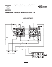
Figure 2 — Typical Switch Mounting