Braun Corporation FMVSS No. 403 Quick Reference Installation Sheet 33675 Rev. A
Maintenance and Lubrication
Hydraulic Fluid (Pump) - Check level. Note: Fluid
should be changed if there is visible contamina-
tion. Inspect the hydraulic system (cylinder, hoses,
�ttings, seals, etc.) for leaks if �uid level is low.
Inspect lifting arm bushings and pivot pins for vis-
ible wear or damage
Inspect outer barrier pivot pin mounting bolts (2)
Mounting
Decals and Antiskid
Use 5606 aviation �uid only (part 87010R-MILL).
Check �uid level with platform lowered fully.
Fill to within 1-1/2" of the bottom of the �ll tube
(neck).
Replace if needed.
Tighten or replace if needed
Check to see that the lift is securely anchored to
the vehicle and there are no loose bolts, broken
welds, or stress fractures.
Replace decals if worn, missing or illegible.
Replace antiskid if worn or missing.
Repeat all previously listed inspection, lubrica-
tion and maintenance procedures at 750 cycle
intervals.
Consecutive
750 Cycle
Intervals
1500
Cycles
4500
Cycles
Apply Light Oil - See Lubrication Diagram
Apply Door Ease - See Lubrication Diagram. Ap-
ply to the surface area around both slots and wipe
off excess
Apply Light Oil - See Lubrication Diagram
Apply Light Oil - See Lubrication Diagram
Apply Synthetic Grease - See Lubrication Diagram
Use compressor and nozzle to remove all debris
from housing. Clean lower pan slot and apply
Antisieze to slot before reinstalling pan.
Use clean cloth and solvent to clean tracks. Clean
lower pan slot and apply Antisieze to slot before
reinstalling pan.
Correct or replace damaged parts and/or relubri-
cate. See Drive Chain Adjustment.
Correct or replace damaged parts and/or relubri-
cate.
Ensure T-handle release and cable assembly
operate properly (see Manual Operation). Ensure
carriage can be manually extended and retracted
freely.
Resecure, replace or adjust as needed. See
Switch Adjustment in service manual.
Correct, replace damaged parts and/or relubricate.
Resecure, replace or correct as needed.
Resecure, replace damaged parts, lubricate or
correct as needed.
Resecure, replace damaged parts, lubricate or
correct as needed. See Carriage Ride Height
Adjustment.
Resecure, replace or correct as needed.
Resecure, replace or correct as needed.
Tighten, repair or replace if needed.
Resecure, repair or replace if needed.
Resecure, replace or correct as needed.
Resecure, replace or correct as needed.
Carriage and eccentric shaft rollers (bearings)
Lifting arm slots in rolling horizontial carriage arm
tubes
Hydraulic cylinder pivot points (4 per cylinder)
Drive chain and chain rollers
Drive chain release latch mechanism
Deploy lift, remove lower pan and blow out hous-
ing. Blow off platform also.
Deploy lift, remove lower pan and clean housing
tracks
Check drive chain tensioner, jam nuts and connect-
ing link for securement and/or misalignment.
Inspect drive chain release latch mechanism for
proper operation, positive securement, wear or
other damage
Inspect platform cable-activated manual release
system (T-handle/cable assembly and carriage
movement)
Inspect limit switches for securement and proper
adjustment
Inspect carriage, lifting arm and eccentric shaft
roller bearings for wear or damage, positive
securement and proper operation
Inspect external snap rings (e-clips):
• Carriage roller bearings (4)
• Lower lifting arm pins (4)
• Eccentric shaft track roller bearing (2)
Inspect lower lifting arm pins for wear or damage,
positive securement and proper adjustment
Inspect eccentric shaft pins, bearing mounting
screw, washers and securement hardware for
wear or damage, positive securement and proper
operation
Inspect torque tube cams for securement, wear or
damage
Inspect housing cam brackets for securement,
wear or damage
Inspect cylinder(s), hoses, �ttings and hydraulic
connections for wear, damage or leaks
Inspect power cable
Inspect handrails for securement
Inspect handrail belts operation, securement wear
or damage.
Adjustments and Diagnostics
T
S
L
V
1
W
S
T
S
L
V
1
W
S
LCD Display Moving Out
Of Cassette
Full Out Moving
Up
At Floor
Level
Moving Down Ground Level
Ground Level
OB Out
STLV SW 1 1
STOW SW 1
FOUT SW 1 1 1 1 1 1
FLV SW 1
OBAR SW 1 1 1 1 1 1 1
SBELT SW = 1 When Seat Belt is Plugged In.
MAT SW = 1 When Mat is Activated
IBAR SW = 1 When IN Barrier is activated
DO SW = 1 When Door is Full Open. Or pin 3 and pin 4 are jumpered.
LO VOLT
Stowed
Drive Chain Adjustment
In event the drive chain sags 1/2" or more, adjust tension
as detailed.
Tighten to eliminate visible sag but do not overtighten.
1. Remove bottom pan.
2. Pull the manual release cable and lock.
3. Remove adjustment bolt (tensioner) access cover.
4. Loosen inside jam nut. Secure tensioner and tighten
outside jam nut. Tighten to eliminate visible chain sag but
do not overtighten.
5. Lock jam nuts together making sure the tensioner roller is
horizontial. Release and push the manual cable in fully.
Ensure platform is locked by moving the platform in and
out until chain release assembly engages chain.
Carriage Ride Height Adjustment
The carriage horizontal arms move (roll) in and out of the
housing tracks on roller bearings. Following installation or
extensive lift operation, clearance between horizontal arms
and tracks may diminish. The eccentric shaft mounting
plate allows height adjustment.
Remove eccentric plate mounting screw. Using screw-
driver or small rod, rotate the shaft clockwise to increase
carriage height. Rotate the shaft counterclockwise to de-
crease carriage height. Reinstall mounting screw in near-
est retainer hole. Adjust left and right side eccentric shafts
(screw positions may vary from side to side). Adjust height
such that horizontal arms do not contact top or bottom of
tracks (align center). For Calibration procedures and Floor
Level Adjustment, see Panel 4 on reverse side.
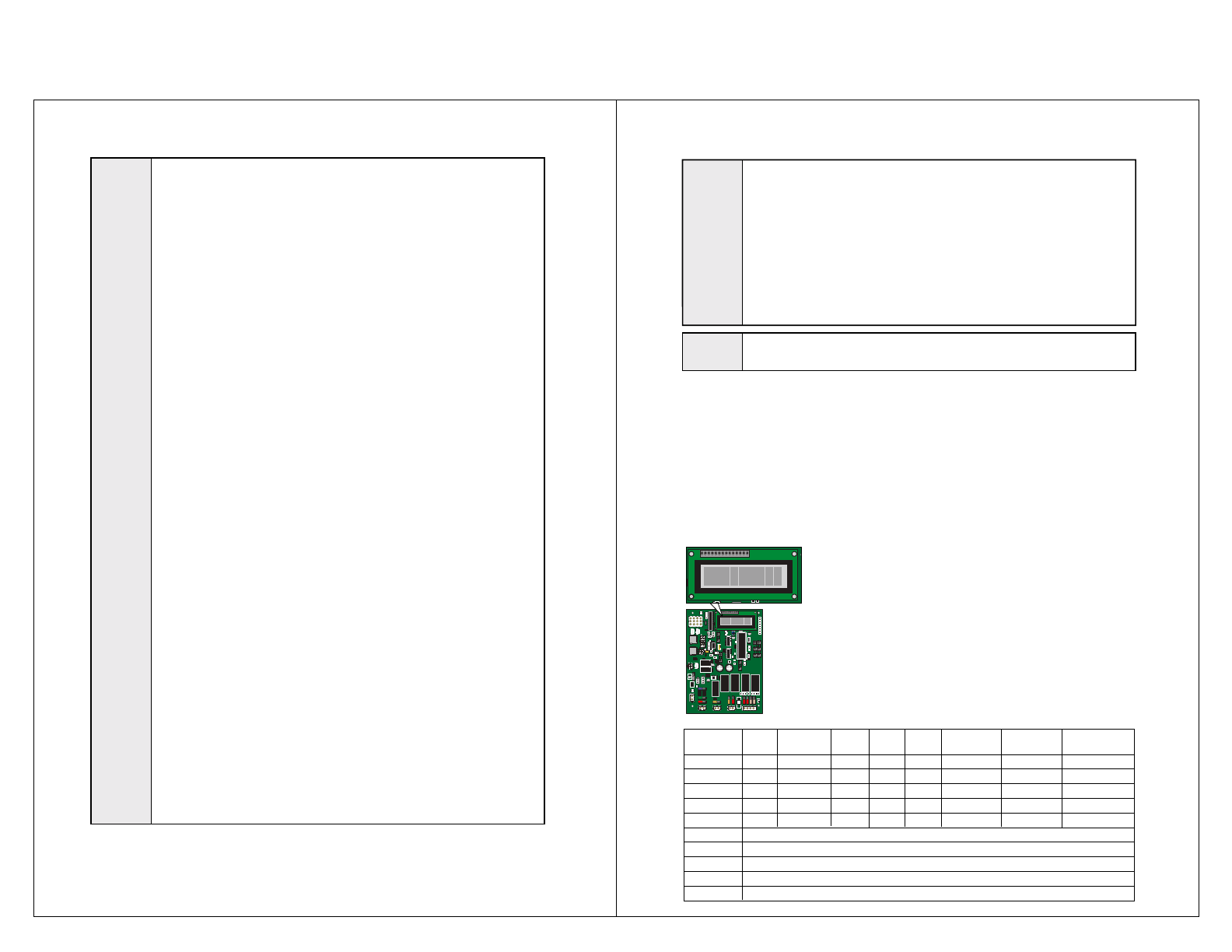
Diagnostics: Following instal-
lation, verify all lift functions and
ensure that the control board
correctly registers the values
listed below when the corre-
sponding action is taken. “1” will
appear on the LCD screen as
shown in the Illustration at right.
If any other value appears on
the LCD screen during the
speci�c diagnostic procedure,
verify that the correct harness is
properly connected to both the
control board and the associ-
ated lift harness. Repeat the
harness diagnostic procedure. If an
incorrect value is still present after
checking the harness and connec-
tions, contact The Braun Corpora-
tion Product Support Department at
1-800-THE-LIFT
®
.
All basic functions (UP, DOWN,
DOOR and STOW) should show
a value of 1 when activated via a
controlled input (Hand-held Pen-
dant, Magnetic, Remote Entry or
3rd Station Controls). Refer to the
service manual for additional switch
and sensor information.
Pump Module
Control Board