


3
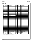
Installation S19-310SS
Bradley Corporation • 215-533 Rev. U; EN 06-532G 6/26/07
Installation Instructions
Supplies Required:
• (3) 3/8" floor anchors and bolts
• Piping to 1-1/4" BSP water supply inlet
• Adequate supply pipe supports
• Piping to 1-1/4" IPS drain outlet on unit
• Minimum 4" drain to accommodate 30 gallons
per minute discharge for drench shower waste
• OPTIONAL: sign mounting hardware
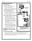
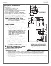
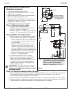
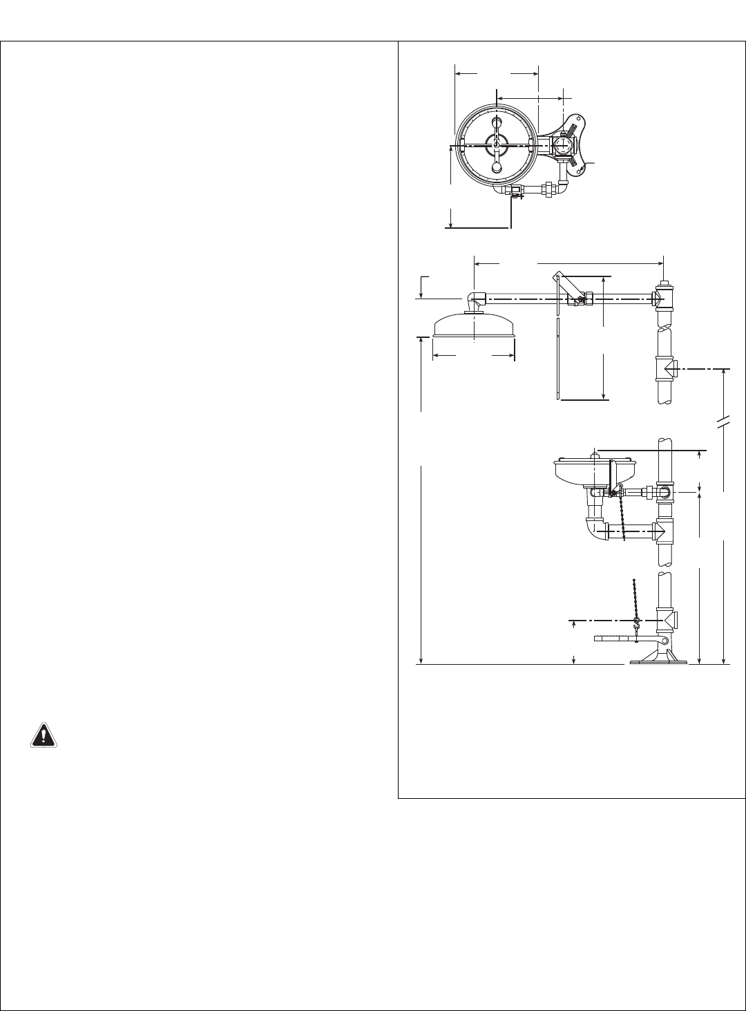
Step 1: Secure base to floor
1. Install three suitable anchors (by installer)
for 3/8" bolts in the floor (see Figure 1).
2. Bolt the base to the floor anchors using 3/8"
bolts (supplied by installer).
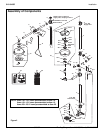
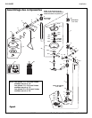
Step 2: Assemble eyewash components
1. Assemble the remaining unit components as
shown in Figure 2 on page 4.
• Apply pipe sealant or tape (supplied by
installer) to all male-threaded pipe joints.
• Use rubber grip pad or strap wrench around
pipes when tightening to prevent marring.
Place grip pad on pipe and then put wrench
over grip pad. With grip pad in place, turn
pipe with wrench.
• The bottom edge of the showerhead should
be 7'-1" (2160mm) from floor.
2. When connecting steel chain, first connect
chain to foot treadle “S” hook. Then with
foot treadle raised up, straighten chain and
connect a link to “S” hook on valve handle.
Make sure steel chain is pulled tight. The
length of chain used will vary.
IMPORTANT: Do not rely on Bradley’s
Combination Unit to support supply
piping.
Step 3: Connect water supply
1. Connect water supply piping to 1-1/4" IPS inlet on unit (piping supplied by installer). Provide
adequate supports (supplied by installer) for supply pipe using pipe hangers or other means.
2. Connect drain piping to 1-1/4" IPS drain outlet on unit (piping supplied by installer).
3. Hang the safety sign from the unit with the curtain hooks provided (or mount it to the wall using
sign-mounting hardware supplied by installer).
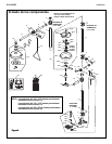
Ø10-3/4"
(273mm)
10-1/2"
(266mm)
9" (229mm)
5-1/8"
(130mm)
Ø10-3/4"
(273mm)
26-3/8"
(670mm)
24"
(610mm)
7'-1"
(2160mm)
TO
FLOOR
66"
(1676mm)
TO
FLOOR
6"
(152mm)
36-3/8"
(924mm)
6"
(152mm)
9" (229mm) DIA. FLANGE
WITH (3) 3/8"DIA. HOLES
ON AN 8" (203mm)
DIA. BOLT CIRCLE
Figure 1
NOTE: All dimensions assume standard thread
engagement.Variations in manufacturing allow
for +/- 1/8" (3mm) per threaded joint.To find
the tolerance of a dimension, add the number
of thread joints in between a dimension and
multiply it by 1/8" (3mm).