


3
Installation E19-310DC
Bradley Corporation • 215-163DCE Rev. Z; EN 06-532F 6/25/07
Installation
Supplies Required:
• (3) M10 floor anchors and bolts
• Teflon tape and pipe sealant
• Piping to 1-1/4" BSP water supply inlet on unit
• Adequate supply pipe supports
• Piping to 1-1/4" BSP drain outlet for eyewash
• Minimum 102mm (4") drain to accommodate
115 liters (30 gallons) per minute discharge for
shower waste
• OPTIONAL: sign-mounting hardware
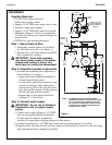
Step 1: Secure base to floor
1. Install three suitable anchors (by installer)
for M10 bolts in the floor (see Figure 1).
2. Bolt the base to the floor anchors using M10
bolts (supplied by installer).
IMPORTANT: Some teflon sealants
may cause stress cracks in the plastic
showerhead leading to failure. Use
teflon tape for sealing the showerhead.
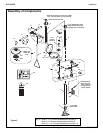
Step 2: Assemble eyewash components
1. Assemble the remaining unit components as
shown in Figure 2 on page 4.
• Apply pipe sealant (supplied by installer) to
all male-threaded pipe joints.
• Use the rubber grip pad provided or a strap
wrench around pipes when tightening to
prevent marring. Place the grip pad on the
pipe, then put the wrench over the grip pad
and turn the pipe with the wrench.
• Bottom edge of showerhead should be
2160mm (7'-1") from floor.
Step 3: Connect water supply
IMPORTANT: Do not rely on Bradley’s
Combination Unit to support supply
piping.
1. Connect water supply piping to 1-1/4" BSP
inlet on unit (piping supplied by installer).
Provide adequate supports (supplied by
installer) for supply pipe using pipe hangers or other means.
2. Connect drain piping to 1-1/4" BSP drain outlet on unit (piping supplied by installer).
3. Hang the safety sign from the unit with the curtain hooks provided (or mount it to the wall using
sign-mounting hardware supplied by installer).
Ø 254mm
(10")
645mm
(25-3/8")
610mm
(24")
2160mm
(7'-1")
To
Floor
1676mm
(66")
To
Floor
140mm
(5-1/2")
1041mm
(41")
152mm
(6")
267mm
(10-1/2")
Ø 273mm
(10-3/4")
247mm
(9-3/4")
Ø 229mm (9") Flange
with (3) Ø 10mm (3/8")
Holes on Ø 203mm (8")
Bolt Circle
133mm
(5-1/4")
Use Teflon
Tape Only
229mm
(9")
Figure 1
NOTE: All dimensions assume standard thread
engagement. Variations in manufacturing allow
for +/- 1/8" (3mm) per threaded joint. To find
the tolerance of a dimension, add the number
of thread joints in between a dimension and
multiply it by 1/8" (3mm).