


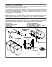

8
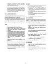
ATTACHING THE CUTTING BLADES
WARNING: Cutting blades are sharp.
Always protect hands by wearing heavy
leather work gloves to grasp blades.
Remove the blades from your tractor’s cutting deck
as follows.
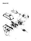
1. Remove the cutting deck from beneath the
tractor, (refer to DECK REMOVAL in the
MAINTENANCE section of your tractor’s
Operator’s Manual for detailed instructions) then
gently flip the deck over to expose its underside.
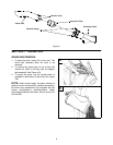
2. Place a block of wood between the center deck
housing baffle and the cutting blade to act as a
stabilizer. See Figure 7.
3. Use a 15/16" wrench to remove the hex flange
nut that secures the blade to the spindle
assembly. See Figure 7.
NOTE: The hex flange nut has a right-handed
thread pattern. Do NOT attempt to force the nut in
the incorrect direction. Doing so may damage the
nut and create a safety hazard.
Figure 7
4. Install the new blades packed with the bagger.
Be sure to install the blade with the side of the
blade marked ‘‘Bottom’’ (or with a part number
stamped in it) facing the ground when the mower
is in the operating position.
IMPORTANT: Mount the smaller of the three
blades to the center spindle. The remaining two
blades are interchangeable.
IMPORTANT: Use a torque wrench to tighten the
blade spindle hex flange nut to between 70 foot-
pounds and 90 foot-pounds.
5. Remount the cutting deck.
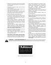
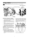
ATTACHING THE DISCHARGE CHUTE
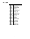
1. Raise the deck to its highest position by placing
the lift lever in the top notch on the right fender.
Raise the chute deflector on the deck.
2. Place the top edge of the discharge chute in
position over the chute opening on the deck,
then push down on the discharge chute so the
front edge fits snugly around the cutting deck
opening. See Figure 8.
Figure 8
3. Fasten the discharge chute in position by
hooking the retainer strap over the retainer clip
on the top* of the deck. See Figure 8.
*NOTE: On later model decks, the retainer clip
may be found on the SIDE or on the FRONT SKIRT
area of the deck rather than on the top of it.
4. Insert the upper end of the chute tube into the
hole in the cover assembly, then insert the
extension tube between the discharge chute and
the chute tube as shown in Figure 9.
5. Secure by placing the ends of the retainer straps
on the discharge chute over the clips on the
chute tube. See Figure 9.
Cutting Blade
Block of Wood
Spindle
Assembly
Hex Flange Nut
Discharge Chute
Chute
Deflector
Cutting Deck
Clip
Retainer
Strap