


CAUSE ACTION
REPLACING THE TRIMMING LINE
Only use the trimming line described in the Specifications section. Other types of
trimming line may cause the engine to overheat or fail.
NOTE: Always use the correct line length when installing trimming line. The line may
not release properly if the line is too long.
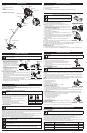
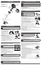
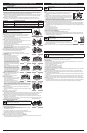
Part 1 - Removing the Inner Reel
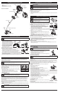
1. Hold the outer spool with one hand and unscrew the bump knob
counterclockwise (Fig. 10).
NOTE: The outer spool will remain attached to the unit.
2. Inspect the bolt inside the bump knob to make sure it moves freely. Replace the
bump knob if it is damaged.
3. Remove the inner reel from the outer spool (Fig. 11).
4. Remove the spring from the inner reel (Fig. 11).
5. Use a clean cloth to clean the inner reel, spring, shaft and inner surface of the
outer spool.
6. Check the indexing teeth and holding slots for wear (Fig. 12). If necessary, remove
burrs or replace the inner reel and outer spool.
Proceed to Part 2 - Winding New Trimming Line onto the Inner Reel.
Part 2 - Winding New Trimming Line onto the Inner Reel
• If using single line, refer to Winding Single Line.
• If using split line, refer to Winding Split Line.
• If using a prewound inner reel, proceed to Part 3 - Installing the Inner Reel.
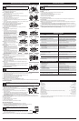
Winding Single Line
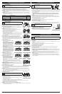
1. Cut two 8-foot (2.4 m) lengths of new single
trimming line.
2. Insert the end of one line into the top hole in
the inner reel (Fig. 13). Wind the line tightly in
the direction shown on the bottom of the inner
reel until about 6 inches (150 mm) of line
remains. Keep the line above the split wall.
Insert the 6-inch section into the nearest .095
holding slot (Fig. 14).
3. Insert the end of the other line into the bottom
hole in the inner reel (Fig. 15). Wind the line
tightly in the direction shown on the bottom of
the inner reel until about 3 to 9 inches (75 to
225 mm) of line remains. Keep the line below
the split wall. Insert the 3 to 9-inch section into
the opposite .095 holding slot (Fig. 16).
NOTE: Failure to wind the line in the direction
indicated will cause the cutting head to operate
incorrectly.
Proceed to Part 3 - Installing the Inner Reel.
Winding Split Line
1. Cut one 6-foot (1.8 m) length of new split line
trimming line. Split each end about 6 inches
(150 mm).
2. Using one split end, insert one line into the top
hole and the other line into the bottom hole in
the inner reel (Fig. 17).
3. Wind the line tightly in the direction shown on
the bottom of the inner reel. The split wall will
automatically divide the line. Wind the line until
it is completely divided and about 6 inches
(150 mm) of line remains.
NOTE: Failure to wind the line in the direction indicated will cause the cutting head to
operate incorrectly.
4. Insert the two 6-inch sections into the two .095 holding slots (Fig. 18).
Proceed to Part 3 - Installing the Inner Reel.
Part 3 - Installing the Inner Reel
1. Pass the two line ends through the eyelets in the outer spool. Place the spring
inside the inner reel. Insert the inner reel into the outer spool. Push the inner reel
and outer spool together (Fig. 19).
NOTE: The spring must be assembled on the inner reel before reassembling the
cutting head.
2. While holding the inner reel and outer spool together, firmly pull the two line ends
to release them from the holding slots.
3. While holding the inner reel and outer spool together, screw the bump knob on
clockwise. Tighten the bump knob securely.
AIR FILTER MAINTENANCE
Cleaning the Air Filter
Failure to maintain the air filter properly can result in poor performance or can cause permanent damage to the engine.
1. Open the air filter cover by pressing the lock tab in and pulling out on the air filter cover (Fig. 20).
2. Remove the air filter (Fig. 20).
3. Wash the filter in detergent and water. Rinse the filter thoroughly and allow it to dry.
4. Apply enough clean SAE 30 motor oil to lightly coat the filter.
5. Squeeze the filter to spread and remove excess oil.
6. Replace the air filter into the air filter cover (Fig. 20).
NOTE: Operating the unit without the air filter WILL VOID the warranty.
7. Close the air filter cover by swinging it to the left and then pressing it down until the lock tab snaps into place (Fig. 20).
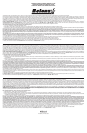
IDLE SPEED ADJUSTMENT
The idle speed of the engine is adjustable. An idle adjustment screw is between the
air filter cover and the engine starter housing (Fig. 21).
NOTE: Careless adjustments can seriously damage the unit. An authorized service
dealer should make carburetor adjustments.
If, after checking the fuel mixture and cleaning the air filter, the engine still will not idle,
adjust the idle speed screw as follows:
1. Start the engine and run for one minute to warm up. Refer to Starting and
Stopping Instructions.
2. Release the throttle trigger and let the engine idle. If the engine stops, insert a small
Phillips screwdriver into the idle adjustment screw (Fig. 21). Turn the idle speed
screw clockwise 1/8 of a turn at a time (as needed) until the engine idles smoothly.
3. If the engine appears to be idling too fast, turn the idle speed screw counterclockwise 1/8 of a turn at a time (as
needed), to reduce idle speed.
Checking the fuel mixture, cleaning the air filter and adjusting the idle speed should solve most engine problems. If not
and all of the following are true:
• the engine will not idle
• the engine hesitates or stalls on acceleration
• there is a loss of engine power
Have the carburetor adjusted by an authorized service dealer.
REPLACING THE SPARK PLUG
Use replacement #753-06193, a Champion RDJ7J spark plug, or equivalent.
1. Stop the engine and allow it to cool. Grasp the plug wire firmly and pull it from the spark plug.
2. Clean around the spark plug. Remove the spark plug from the cylinder head by
turning a 5/8-inch socket counterclockwise.
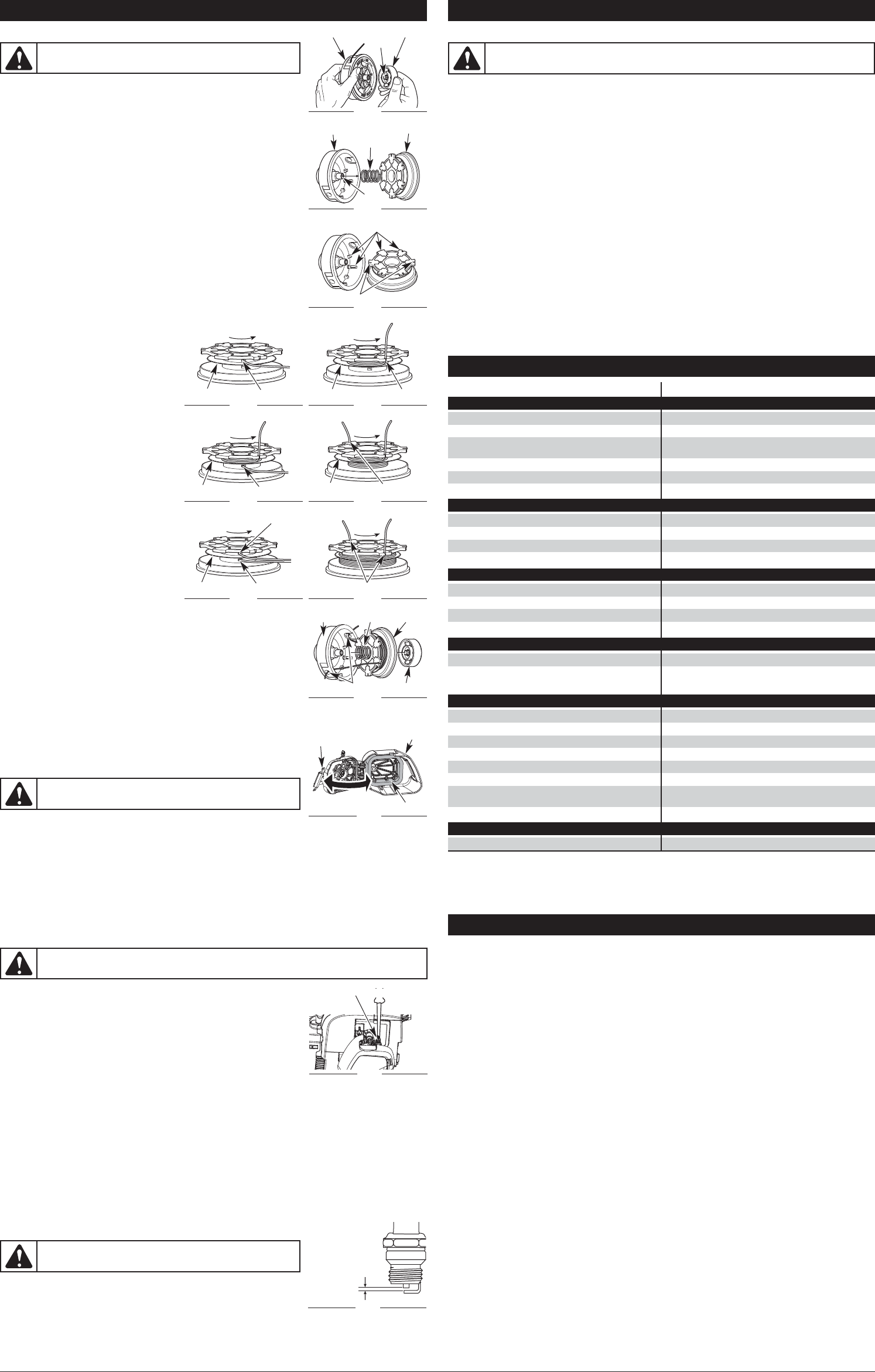
3. Replace a cracked, fouled or dirty spark plug. Set the air gap at 0.025 in. (0.635 mm)
using a feeler gauge (Fig. 22).
4. Install a correctly-gapped spark plug in the cylinder head. Tighten by turning the
5/8-inch socket clockwise until snug.
NOTE: If using a torque wrench, torque to: 110-120 in.•lb. (12.3-13.5 N•m). Do not over tighten.
4
MAINTENANCE AND REPAIR INSTRUCTIONS
WARNING:
To avoid serious personal injury, always turn the unit
off and allow it to cool before you clean or service it.
WARNING:
The cutting attachment will spin during idle speed adjustments. Wear protective clothing
and observe all safety instructions to prevent serious personal injury.
WARNING: Do not sand blast, scrape or clean electrodes. Grit in the
engine could damage the cylinder.
Fig. 22
0.025 in.
(0.635 mm.)
WARNING:
Never use metal-reinforced line, wire, chain or rope.
These can break off and become dangerous projectiles.
Fig. 21
Idle Adjustment Screw
The fuel is old (over 30 days) and/or improperly mixed Drain the fuel tank and add fresh, properly mixed fuel
Fouled spark plug Replace or clean the spark plug
The fuel is old (over 30 days) and/or improperly mixed Drain the fuel tank and add fresh, properly mixed fuel
Cutting head bound with grass Stop the engine and clean the cutting head
Dirty air filter Clean or replace the air filter
Empty fuel tank Fill fuel tank with properly mixed fuel
The primer bulb wasn't pressed enough Press the primer bulb 10 times or until fuel is visible
Engine is flooded
With the choke lever in position 3, squeeze the trigger
and pull the starter rope
The fuel is old (over 30 days) and/or improperly mixed Drain the fuel tank and add fresh, properly mixed fuel
Fouled spark plug Replace or clean the spark plug
Cutting head bound with grass Stop the engine and clean cutting head
Cutting head out of line Refill with new line
Inner reel bound up Rewind the inner reel
Cutting head dirty Clean inner reel and outer spool
Line welded Disassemble, remove the welded section and rewind
Line twisted when refilled Disassemble and rewind the line
Not enough line is exposed
Push the bump knob and pull out line until 4 inches (102 mm)
of line is outside of the cutting head
Oil, cleaner or lubricant in cutting head Clean and thoroughly dry the cutting head
Air filter is plugged Replace or clean the air filter
The fuel is old (over 30 days) and/or improperly mixed Drain the fuel tank and add fresh, properly mixed fuel
Improper idle speed Adjust the idle speed
TROUBLESHOOTING
ENGINE WILL NOT START
ENGINE WILL NOT IDLE
ENGINE WILL NOT ACCELERATE
IF FURTHER ASSISTANCE IS REQUIRED, CONTACT AN AUTHORIZED SERVICE DEALER.
ENGINE LACKS POWER OR STALLS
CUTTING LINE ADVANCES UNCONTROLLABLY
CUTTING HEAD WILL NOT ADVANCE LINE
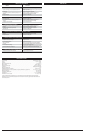
Engine Type. . . . . . . . . . . . . . . . . . . . . . . . . . . . . . . . . . . . . . . . . . . . . . . . . . . . . . . . . . . . . . . . . . . . . Air-Cooled, 2-Cycle
Stroke . . . . . . . . . . . . . . . . . . . . . . . . . . . . . . . . . . . . . . . . . . . . . . . . . . . . . . . . . . . . . . . . . . . . . . . . . . . . 1.02 in. (2.6 cm)
Displacement. . . . . . . . . . . . . . . . . . . . . . . . . . . . . . . . . . . . . . . . . . . . . . . . . . . . . . . . . . . . . . . . . . . . . . . . . . . . . . . 25 cc
Operating RPM . . . . . . . . . . . . . . . . . . . . . . . . . . . . . . . . . . . . . . . . . . . . . . . . . . . . . . . . . . . . . . . . . . . . . . . . 6,300+ rpm
Idle Speed RPM. . . . . . . . . . . . . . . . . . . . . . . . . . . . . . . . . . . . . . . . . . . . . . . . . . . . . . . . . . . . . . . . . . . 3,200 - 4,400 rpm
Spark Plug Gap . . . . . . . . . . . . . . . . . . . . . . . . . . . . . . . . . . . . . . . . . . . . . . . . . . . . . . . . . . . . . . . . . 0.025 in. (0.635 mm)
Lubrication . . . . . . . . . . . . . . . . . . . . . . . . . . . . . . . . . . . . . . . . . . . . . . . . . . . . . . . . . . . . . . . . . . . . . . . . Fuel/Oil Mixture
Fuel/Oil Ratio . . . . . . . . . . . . . . . . . . . . . . . . . . . . . . . . . . . . . . . . . . . . . . . . . . . . . . . . . . . . . . . . . . . . . . . . . . . . . . . . 40:1
Fuel Tank Capacity. . . . . . . . . . . . . . . . . . . . . . . . . . . . . . . . . . . . . . . . . . . . . . . . . . . . . . . . . . . . . . . . . 10 fl. oz. (296 ml)
Approximate Unit Weight (No fuel, with cutting attachment, shield and D-handle). . . . . . . . . . . . 10 - 11 lbs. (4.5 - 5 kg)
Cutting Mechanism. . . . . . . . . . . . . . . . . . . . . . . . . . . . . . . . . . . . . . . . . . . . . . . . . . . . . . . . . . . . . . . . . . . Bump Head™
Line Spool Diameter . . . . . . . . . . . . . . . . . . . . . . . . . . . . . . . . . . . . . . . . . . . . . . . . . . . . . . . . . . . . . . . . . . 3 in. (76.2 mm)
Trimming Line Diameter. . . . . . . . . . . . . . . . . . . . . . . . . . . . . . . . . . . . . . . . . . . . . . . . . . . . . . . . . . . . 0.095 in. (2.41 mm)
Cutting Path Diameter . . . . . . . . . . . . . . . . . . . . . . . . . . . . . . . . . . . . . . . . . . . . . . . . . . . . . . . . . . . . . . . 17 in. (43.18 cm)
SPECIFICATIONS*
* All specifications are based on the latest product information available at the time of printing. We reserve the right to
make changes at any time without notice.
Fig. 20
Air Filter Cover
Air Filter
Lock Tab
CLEANING AND STORAGE
CLEANING
Use a small brush to clean off the outside of the unit. Do not use strong detergents. Household cleaners that contain
aromatic oils such as pine and lemon, and solvents such as kerosene, can damage plastic housing or handle. Wipe off
any moisture with a soft cloth.
STORAGE
• Never store a fueled unit where fumes may reach an open flame or spark.
• Allow the engine to cool before storing.
• Store the unit locked up to prevent unauthorized use or damage.
• Store the unit in a dry, well-ventilated area.
• Store the unit out of the reach of children.
Short Term Storage (1-2 weeks)
1. Store the unit in a horizontal position. If this is not possible, store the unit vertically with the engine at the top.
Long-term Storage
1. Remove the fuel cap, tip the unit and drain the fuel into an approved container.
NOTE: Do not use gasoline that has been stored for more than 30 days. Dispose of old gasoline in accordance with
federal, state and local regulations.
2. Start the engine and allow it to run until it stalls. This ensures that all fuel has been drained from the carburetor.
3. Allow the engine to cool. Remove the spark plug and put 5 drops of any high quality motor oil or 2-cycle oil into the
cylinder. Pull the starter rope slowly to distribute the oil. Reinstall the spark plug.
NOTE: Remove the spark plug and drain all of the oil from the cylinder before attempting to start the unit after storage.
4. Thoroughly clean the unit and inspect it for any loose or damaged parts. Repair or replace damaged parts and
tighten loose screws, nuts or bolts. The unit is ready for storage.
WARNING:
To avoid serious personal injury, always turn the unit off and allow it to cool before you
clean or service it.
Holding Slot
Fig. 14
Fig. 16
Holding Slots
Fig. 18
Indexing Teeth
Fig. 12
Outer Spool
Fig. 19
Bolt
Outer Spool
Fig. 10
Outer Spool
Spring
Inner Reel
Fig. 11
Bump Knob
Shaft
Holding Slots
Top Hole
Fig. 13
Fig. 15
Top Hole
Fig. 17
Split Wall
Split Wall
Bottom Hole
Split Wall
Holding SlotSplit Wall
Bottom Hole
Split Wall
Inner Reel
Bump Knob
Spring
Eyelets