


10
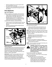
Operating Tips
NOTE: Allow the engine to warm up for a few minutes
as the engine will not develop full power until it reaches
operating temperature.
WARNING: Muffle, engine, and surround-
ing areas become hot and can cause a
burn. Do not touch.
• Set the skid shoes 1/4" below the shave plate for
normal usage. The skid shoes may be adjusted
upward (to lower the shave plate) for hard-packed
snow. Adjust downward (to raise the shave plate)
when using on gravel or crushed rock.
• For most efficient snow removal, remove snow
immediately after it falls.
• Discharge snow downwind whenever possible and
slightly overlap each previous cleared path.
• Follow the precautions found under the heading To
Stop Engine to prevent possible freeze-up.
• Clean the snow thrower thoroughly after each use.
SECTION 5: MAKING ADJUSTMENTS
WARNING: NEVER attempt to make any
adjustments while the engine is running,
except where specified in the operator’s
manual.
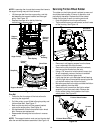
Chute Assembly Adjustment
The distance snow is thrown can be adjusted by
adjusting the angle of the chute assembly. Refer to the
Chute Tilt Control in the Know Your Snow Thrower
Section.
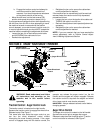
Chute Directional Control And Support
Bracket Adjustment
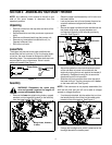
If the spiral at the base of the chute directional control is
not fully engaging with the notches in the lower chute
assembly, the support bracket can be adjusted inward
or outward as follows:
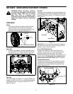
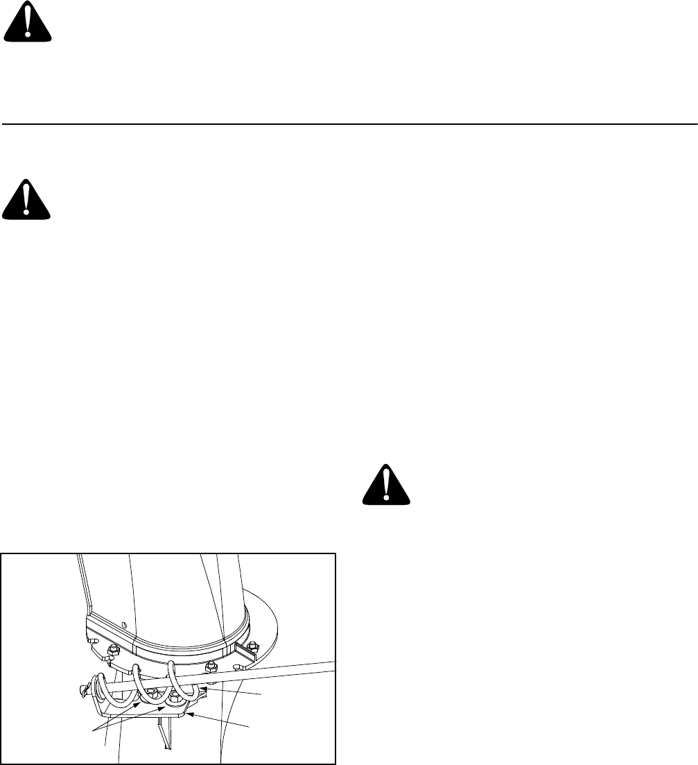
• Loosen, but do NOT remove the two hex nuts
which secure the chute directional control support
bracket to the snow thrower housing. See Figure 8.
Figure 8
• Adjust the support bracket inward or outward so
that the spiral is fully engaged in the notches on the
chute before retightening the hex nuts.
Skid Shoe Adjustment
The space between the shave plate and the ground can
be adjusted by raising or lowering the skid shoes. Refer
to Skid Shoe Adjustment in the Assembly Section.
Auger Control Adjustment
Refer to the information found under Final
Adjustments in the Assembly Section to adjust the
auger control.
Traction Control Adjustment
Refer to the information found under Final Adjustments
in the Assembly Section to adjust the traction control. If
you are uncertain that you have reached the correct
adjustment, proceed as follows:
WARNING: Drain the gasoline out of your
snow thrower’s engine or place a piece of
plastic film under the gas cap to avoid
spillage BEFORE beginning to perform
this adjustment.
• Tip the snow thrower forward, allowing it to rest on
the auger housing.
• Remove the frame cover underneath the snow
thrower by removing six self-tapping screws.
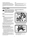
With the traction control released, there must be
clearance between the friction wheel and the drive plate
in all positions of the shift lever.
With the traction control engaged, the friction wheel
must contact the drive plate. See Figure 9.
If adjustment is necessary:
• Loosen the jam nut on the traction drive cable and
thread the cable in or out as necessary.
• Retighten the jam nut to secure the cable when
correct adjustment is reached.
• Reassemble the frame cover.
NOTE: If you placed plastic film under the gas cap, be
certain to remove it before operating the snow thrower.
Spiral
Support
Bracket
Hex Nuts