


Assembly
2
Section
6
INTRODUCTION
Carefully follow these assembly steps to
correctly prepare your tiller for use. It is
recommended that you read this Section
in its entirety before beginning assembly.
NOTE: Various tiller models are presented
in this Manual. Use only the information
appropriate for your tiller model.
INSPECT UNIT
Inspect the unit and carton for damage
immediately after delivery. Contact the
carrier (trucking company) if you find or
suspect damage. Inform them of the
damage and request instructions for filing
a claim. To protect your rights, put your
claim in writing and mail a copy to the car-
rier within 15 days after the unit has been
delivered. Contact the factory if you need
assistance in this matter.
TOOLS/MATERIALS NEEDED
FOR ASSEMBLY
(1) 3/8” open-end wrench*
(2) 7/16" open-end wrench*
(2) 1/2" open-end wrench*
(2) 9/16" open-end wrench*
(1) Scissors (to trim plastic ties)
(1) Ruler (for belt tension check)
(1) Block of wood (to support tiller
when removing wheels)
(1) Tire pressure gauge (for models with
pneumatic tires)
(1) Clean oil funnel
(1) Motor oil. Refer to the Engine Owner’s
Manual for oil specifications and
quantity required.
* Adjustable wrenches may be used.
ASSEMBLY STEPS
STEP 1: UNPACKING INSTRUCTIONS
NOTE: While unpacking, do not severely
bend any control cables.
1. The tiller weighs approximately 133 lbs.
Do not attempt to remove it from the ship-
ping platform until instructed to do so in
these Assembly steps.
2. Remove any packaging material from
the carton. Remove any staples from the
bottom of the carton and remove the
carton from the shipping platform.
3. Remove all unassembled parts and the
separate hardware bag from the carton.
Check that you have the items listed in the
Loose Parts List (contact your local dealer
if items are missing or damaged).
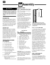
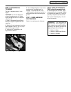
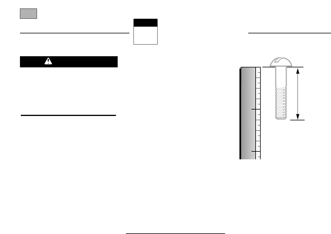
NOTE: Use the screw length template
(Fig. 2-1) to identify screws.
Loose Parts List
Qty. Description
1 Handlebar Support (see A, Fig. 2-2)
1 Handlebar Assembly (see K, Fig. 2-2)
Hardware bag contents:
1 Slotted hd. screw, #10-24 x 2"
1 Hex hd. screw, 1/4-20 x 1-1/4"
6 Hex hd. screw, 5/16-18 x 1-1/2"
2 Hex hd. screw, 3/8-16 x 3/4"
2 Flat washer, 3/8"
6 Split lockwasher, 5/16"
1 Hex locknut, 1/4"-20
6 Hex nut, 5/16"-18
1 Hex nut, #10-24
2 Hex locknut, 3/8"-16
1 Spring, cable (see W, Fig. 2-5)
1 Bracket, forward clutch cable (see
P, Fig. 2-4)
IMPORTANT: Motor oil must be added to
the engine crankcase before the engine is
started. Follow the instructions in this
Assembly Section and in the separate
Engine Owner’s Manual.
NOTE: LEFT and RIGHT sides of the tiller
are as viewed from the operator’s position
behind the handlebars.
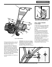
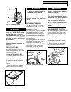
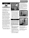
STEP 2: ATTACH HANDLEBAR
1. Loosely attach the legs of the handlebar
support (A, Fig. 2-2) to the inner sides of
the tiller frame using two 3/8"-16 x 3/4"
hex hd. screws (B), 3/8" flat washers (C)
and 3/8"-16 hex locknuts (D).
2. There are three height adjustment holes
in the two handlebar support brackets (E
and F, Fig. 2-2). Use a setting that will
position the handlebars at approximately
waist level when the tines are 3"-4" into the
soil. Loosely attach the support brackets
to the handlebar support (A) using two
5/16"-18 x 1-1/2" screws (G), 5/16" split
lockwashers (H) and 5/16"-18 hex nuts (I).
NOTE: If a support bracket will not move,
loosen attaching screw (J) and nut.
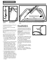
3. Attach the handlebar assembly (K) to
the handlebar support (A) using four
5/16"-18 x 1-1/2" screws (G), 5/16" split
lockwashers (H) and 5/16"-18 hex nuts (I).
Tighten the four screws securely.
4. Tighten all handlebar mounting hard-
ware securely.
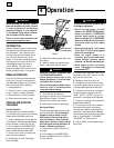
STEP 3: MOVE TILLER OFF
SHIPPING PLATFORM
To roll the tiller off the shipping platform,
put the wheels in FREEWHEEL, as follows:
1. Place a sturdy block under the trans-
mission to raise one wheel about 1" off the
ground.
To prevent personal injury or property
damage, do not start the engine until
all assembly steps are complete and
you have read and understand the
safety and operating instructions in this
manual.
WARNING
1
2
1
2
Figure 2-1: To identify length of screws,
place screw on template as shown and mea-
sure distance between bottom of screw head
and tip of screw.