


Installation (continued)
6. Testing Performance
@ Test Shore Power
Connect the shore power cable to the shore power source. Turn
on the shore source to make power available to the boat.
a. Turn the selector switch to SHORE. No Reverse
Polarity lights should be lit, and power available should
be indicated. If any red Reverse Polarity lights are on,
turn off the shore power circuit breaker and disconnect
the shore cord at the shore source. Either the hot and
neutral or hot and ground wires have been reversed.
Starting at the distribution panel, trace the connections
as far back as necessary to locate the error.
b. If there are no indications of reverse polarity, check to
see that power is available. If the electrical distribution
panel has a meter, verify that shore power is available
and at the proper voltage. If there is no meter, turn
on the load circuit breaker for an AC circuit powering
a convenience outlet and use a voltmeter to verify
that power is available from line to neutral at the plug.
Verify that there is no voltage between ground and
neutral.
@ Test Generator System
Turn the circuit breaker at the shore source to OFF. Set the
selector switch to OFF. The shore power available lights should
all be off. Start the generator and turn the generator breaker to
ON.
a. The power available light for the generator output
should light. The reverse polarity light should be off.
b. There should be no power available indication at the
shore power circuit breaker.
c. Set the selector switch to GENERATOR. Power
should be available at the power distribution panel. If
the electrical distribution panel has a meter, verify that
power is available and at the proper voltage.
d. There should be no power available lights indicating at
the shore circuit breaker, or the shore indicator of this
panel.
The Purpose of the AC Main Source Selector Panel
Alternating Current (AC) power changes polarity 60 times per second in
the US, Canada and Latin America and 50 times per second in Europe.
This is the frequency of the power and is referred to as Hertz (or the now
outdated term “cycle”). Because of this alternating nature of AC power,
two live sources of AC power, such as shore power and inverter power,
or shore power and a generator, cannot be electrically connected. The
AC Main Source Selector panel is designed to connect two sources of
AC power to a common circuit while preventing both sources from being
connected to the circuit simultaneously.
Related Products from Blue Sea Systems
• High Amperage Fuses and Circuit Breakers for positive feed wires
• High Amperage Battery Switches
• Terminal Blocks and Common Bus Connectors
• AC Distribution Panels
• DC Distribution Panels
• AC and DC Digital and Analog Voltmeters and Ammeters
Useful Reference Books
Calder, Nigel, 1996: Boatowner’s Mechanical and Electrical Manual,
2nd edition, Blue Ridge Summit, PA: TAB Books, Inc.
Wing, Charlie, 1993: Boatowner’s Illustrated Handbook of Wiring,
Blue Ridge Summit, PA: TAB Books, Inc.
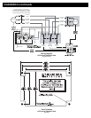
@ Test Shore Connection to Switch
Disconnect the shore power cord from the shore power source
and bring the shore plug aboard to a point close to the switch
panel. Connect the other end of the shore cord to the boat’s
power inlet. Turn ON the shore power circuit breaker between the
inlet and the selector switch. Set the selector switch to OFF.
a. Use an ohmmeter to check for continuity from the shore
ground plug to the green wire at the electrical panel.
b. Check for continuity from the power cord plug neutral
pin to the neutral wire at the selector switch. [7]
c. Check for continuity between each line pin of the shore
plug and the line wire at the selector switch. [3], [11]
d. Check that there is a high resistance between (>1000
Ohms) the neutral conductor and the grounding
conductor.
e. Verify that there is a high resistance between (>1000
Ohms) between the shore cord plug neutral pin and
each line pin. There may be indicator lamps in the
circuit, but no more than that with the selector switch in
the off position.
@ Verify Switch Selects Shore Input
With the shore cord still disconnected from the shore and
available onboard, and the generator set not operating, set the
load circuit breakers to off, so there is no load at the output side of
the selector switch.
a. Verify that the there is a high resistance between each
line and neutral of the load side terminals of the
selector switch. There may be indicator lamps still
attached, so it may not read open circuit. [2] to [6], [6]
to [10]
b. Set the selector switch to SHORE. The ohmmeter
should still indicate a high resistance, for the same
tests.
c. Short each line pin to the neutral pin of the shore cord
and verify that each line and neutral at the load side of
the selector show a low resistance when these are
shorted and a high resistance when they are not.
@ Verify the Generator Wiring
Turn the generator circuit breaker to OFF and set the selector
switch to the generator position. All load circuit breakers should
still be off. Leave the shore input circuit breaker in the on
position.
a. Verify that there is a high resistance (>1000 Ohms)
from each line to neutral. [2] to [6], [6] to [10]
b. Verify that there is a low resistance from the neutral to
ground at the load connections. [6] to [ground]
c. With the generator still not running, close the generator
circuit breaker at the generator. Verify that there is a
now a low resistance from each line to neutral where
the generator windings are now connected across the
circuit.
d. Verify that there is still a high resistance from neutral
to ground and neutral to each line at the shore power
plug.
@ Set the Selector switch to OFF, turn the shore power breaker
to OFF, and leave the load panel circuit breakers in the OFF
position.
Set your multimeter to volts.
5. Apply circuit labels and mount panel
Apply a label for the circuit form the 10 basic labels provided. If the
appropriate label is not included individual labels are available form
Blue Sea Systems for specifi c applications. Refer to the label order
form included with the panel for a complete listing of individual labels.
Fasten the panel to the mounting surface using the panel mounting
screws supplied with the panel.