


LED
1
2
3
+8
-7
LED
1
2
3
+8
-7
2
AMP MIN.
A
B
START
BATTERY
2155
REMOTE CONTROL SWITCH
SPDT, ON-ON
ENGINE
NOTE: For optional SPST
switch connections
Wire connections are the same
as the SPDT, ON-ON except
the Ground is omitted.
No Connection
orange
green
brown
CONTROL (red)
GROUND (black)
LED OUTPUT (yellow)
+12V DC (red)
1
2
3
6
4
2
AMP MIN.
A
B
START
BATTERY
2155
REMOTE CONTROL SWITCH
SPDT, ON-ON
ENGINE
NOTE: For optional SPST
switch connections
Wire connections are the same
as the SPDT, ON-ON except
the Ground is omitted.
GROUND (black)
LED OUTPUT (yellow)
+12V DC (red)
CONTROL (red)
1.965"
49.91mm
1.010"
25.65mm
.595"
15.10mm
1.125"
28.58mm
TEST CUT
HOLE IN
ACTUAL
CENTER
1.450"
36.83mm
0.830"
21.08mm
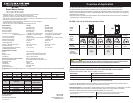
InstallationInstructions
InstallationInstructions
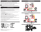
Mounting
Install as close as possible to battery bank. To avoid corrosion to connecting wires and terminals, mount in
a dry and protected location. Avoid mounting directly above vented lead acid batteries so that the Remote
Battery Switch is not exposed to corrosive gasses expelled from the batteries.
HighCurrentPrimaryCircuitConnections (studterminalsAandB)
For help selecting the appropriate wire size and circuit protection rating, go to www.bluesea.com and click the
Circuit Wizard quick link.
NOTE: Stud terminals A and B are interchangeable. A battery connection is required on one terminal
for device operation
Toconnecthighcurrentcircuitwires:
1. Connect the battery bank to one of the stud terminals marked A or B.
2. Connect the load to the other stud terminal marked B or A.
3. Torque the high current terminal stud nuts to 140 in-lbs (15.5 N•m) maximum.
NOTE: If switching an inverter, windlass, bow thruster, etc., the circuit wires must have circuit protection to
comply with ABYC guidelines. Wires used for engine starting do not require circuit protection.
ControlCircuitConnections (wirescontainedinthewireharness)
NOTE: The Remote Battery Switch is designed to be controlled by a SPDT or SPST switch.
Use minimum 16 AWG wire for the Control Circuits. For help selecting the appropriate wire size for the load
cables, go to www.bluesea.com and click the Circuit Wizard quick link.
ToconnecttheSPDTRemoteControlSwitch2155:
1. Connect pin 3 and pin 8 to +12V or +24V Power available when Remote Battery Switch is OFF. (fused)
2. Connect the red control wire to switch pin 2.
3. Connect pin 7 to yellow wire.
4. Connect pin 1 to ground or negative.
4.50"
114.30mm
3.00"
76.20mm
5.47"
138.94mm
3.75"
95.25mm
2.03"
51.56mm
1.90"
48.26mm
1.03"
26.16mm
Guarantee
Blue Sea Systems stands behind its products for as long as you own them.
Find detailed information at www.bluesea.com/about.
For customer service, call 800-222-7617.
These instructions are intended to provide assistance with the installation of this product, and are
not a substitute for a more comprehensive understanding of electrical systems. We strongly
recommend that a competent electrical professional perform the installation of this product.
The illustrated wiring diagram represents a common installation and is not meant to be a guide for wiring
a specic vessel. The wiring diagram shows a single battery bank installation.
Disconnect all negative battery connections before beginning the installation.
All unused control wires should be carefully insulated from each other and from accidental contact
using heat shrink tubing or electrical tape. External contact or shorting between control wires can lead
to malfunction.
CAUTION
TinnedWireTermination
DeutschDTMConnectorTermination