


ADDITIONAL BREAKER
REQUIRED IF GREATER
THAN 10 FEET
CONNECT
TO AC HO
T
LOAD(S)
NEUTRA
L
PIGTAIL
LINE 1
LOAD 1
N
N
S
E
N
S
O
R
C
O
I
L
TO AC SAFETY GROUND SOURCE
DC BACKLIGHT
BOARD
FROM DEVICE
SAFETY
GROUND
FROM DEVICE
NEUTRAL
FUSE 1.0 TO 2.0A
AC SAFETY
GROUND BUS
AC NEUTRAL
BUS
R.P.
LED
LED
FROM AC HOT SOURCE
FROM AC NEUTRAL SOURCE
SHORE
POWER
INLET
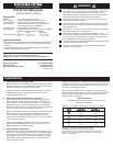
Installation(continued)
4. Installfeedcircuitwires
Install the feed wires from the shore power inlet or other AC source,
referring to the wire sizing chart to select the correct wire size. Connect
the black AC hot, white AC neutral and green AC safety ground as
shown in the illustration.
If the feed wires are from the shore power inlet or the electrical
attachment point of a permanently installed shore power cord and the
inlet or attachment point is more than 10 feet from this panel, additional
fuses or circuit breakers must be installed within 10 feet of the shore
power inlet. The measurement is made along the conductors.
5. InstallationofBacklightSystem
The backlight board is a DC device. When installing it in an AC panel
both wire leads must be connected to an appropriate DC source
and ground.
Connect the yellow negative wire to a DC ground. Connect the red
positive wire to a DC positive supply, usually a switch that controls
the vessel’s other nighttime illumination.
6. Applybranchcircuitlabelsandmountpanel
Apply a label for each circuit from the label set provided. Extended
label sets are available through retail suppliers, and over 500 individual
labels are available directly from Blue Sea Systems. Please go to
www.bluesea.comtoorderindividuallabelsforspecicapplications.
Fasten the panel to the mounting surface using the screws provided.
7. Testing
Connect the vessel’s shore power and verify the Reverse Polarity
light is not illuminated. If the red Reverse Polarity light is on then
either the hot and ground or the hot and neutral wires have been
crossed. Starting at the panel, trace the connections back as far as
necessary to locate the error.
Using a multimeter where the power source is connected to the
panel verify:
a. 120 volts between hot and neutral
(nominal, this may vary depending on source voltage)
b. 120 volts between hot and ground.
c. 0 volts between neutral and ground.
Turn on each branch circuit to verify power to each circuit.
Refer to Carling Technologies™ PB-Series ELCI/RCBO installation
Bulletin for Marine Main Circuit Protection, (IST-0006), for test
procedure and frequency.
8. OptionalBranchLEDs
This Panel is supplied with LEDs pre-installed in all optional branch
positions. For future expansion of the panel remove the hot leg of the
LED from the AC Neutral Bus and connect it to the Load side of the
branch circuit breaker.
Note
Blue Sea Systems’ 8101 and 8102 electrical distribution panels
are furnished with two 15A AC branch circuits. This rating will satisfy
the vast majority of marine circuit protection situations.
RelatedProductsfromBlueSeaSystems
•360PanelSystem
•Batterymanagementsolutions
•ACandDCcircuitprotectiondevices
•WeatherDeck™ waterproof circuit breaker panels
•Fuses,fuseblocks,andBusBars
•Analoganddigitalmeters
UsefulReferenceBooks
•Calder,Nigel(2005).Boatowner’s Mechanical and Electrical Manual
(3d ed). Camden ME: International Marine / McGraw-Hill.
•Wing,Charlie(2206).Boatowner’s Illustrated Electrical Handbook
(2d ed). Camden ME: International Marine / McGraw-Hill.
Keepallsuppliedinstructionswithboatsystemrecords
forfuturereference.
ADDITIONAL BREAKER
REQUIRED IF GREATER
THAN 10 FEET
LINE 1
LOAD 1
N
N
S
E
N
S
O
R
C
O
I
L
TO AC SAFETY GROUND SOURCE
DC
BACKLIGHT
BOARD
FROM
DEVICE
SAFETY
GROUND
FROM
DEVICE
SAFETY
GROUND
FROM
DEVICE
NEUTRAL
R.P.
LED
LED
LED
LED
LED
LED
LED
AC SAFETY GROUND BUS
AC NEUTRAL BUS
FROM AC HOT SOURCE
FROM AC NEUTRAL SOURCE
SHORE
POWER
INLET
NEUTRAL
PIGTAIL
TO DC
NEGATIVE
FROM DC
POSITIVE
TO DEVICE
HOT
TO DEVICE
HOT
15A
15A
BRANCH
CIRCUIT
R.P.
LED
FUSE
DC
BACKLIGHT
BOARD
1.0TO 2.0A
AC
VOLTMETER
+12V
+24V
-Ne
g
Red
Orange
Yellow
LED
LED
LED
LINE 1
LOAD 1
N
N
AC NEUTRAL BUS
FROM
DEVICE
NEUTRAL
S
E
N
S
O
R
C
O
I
L
TO AC SAFETY GROUND SOURCE
FROM AC HOT SOURCE
FROM AC NEUTRAL SOURCE
SHORE
POWER
INLET
ADDITIONAL BREAKER
REQUIRED IF GREATER
THAN 10 FEET
NEUTRAL
PIGTAIL
FROM
DEVICE
SAFETY
GROUND
AC SAFETY GROUND BUS
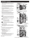
WiringDiagramPN8102-120V AC ELCI Panel, 30A Main, 2 Position, Voltmeter
WiringDiagramPN8101-120V AC ELCI Panel, 30A Main, 5 Position
WiringDiagramPN8100-120V AC ELCI Panel, 30A Main