


b. Check to see if receptacle is connected to a light switch
which turns power off when you turn out the lights.
c. Move charger and battery pack to a location where the
surrounding air temperature is approximately 60°F - 80°F
(16° - 27°C).
d. If charging problems persist, take the tool, battery pack and
charger to your local service center.
4. The battery pack should be recharged when it fails to produce
sufficient power on jobs which were easily done previously. DO
NOT CONTINUE to use under these conditions. Follow the charging
procedure. You may also charge a partially used pack whenever
you desire with no adverse affect on the battery pack.
5. Foreign materials of a conductive nature such as, but not limited
to, steel wool, aluminum foil, or any buildup of metallic particles
should be kept away from charger cavities. Always unplug the
charger from the power supply when there is no battery pack in the
cavity. Unplug charger before attempting to clean.
6. Do not freeze or immerse charger in water or any other liquid.
WARNING: Shock hazard. Do not allow any liquid to get
inside charger. Never attempt to open the battery pack for any
reason. If the plastic housing of the battery pack breaks or cracks,
return to a service center for recycling.
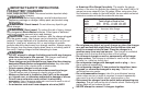
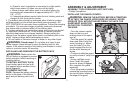
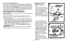
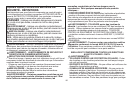
INSTALLING AND REMOVING THE BATTERY PACK
WARNING: Make certain the
lock-off button is engaged to prevent
switch actuation before removing or
installing battery.
TO INSTALL BATTERY PACK:
Insert battery pack into tool until
fully seated and an audible click is
heard (figure 2).
TO REMOVE BATTERY
PACK: Depress the battery release
button in the back of the battery
pack and pull battery pack out of
tool.
7
ASSEMBLY & ADJUSTMENT
ASSEMBLY TOOLS REQUIRED (NOT SUPPLIED):
- Phillips Screwdriver
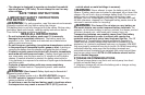
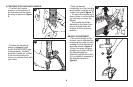
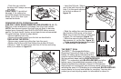
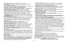
INSTALLING THE GUARD- FIGURE 3
WARNING: REMOVE THE BATTERY BEFORE ATTEMPTING
TO ATTACH THE GUARD, EDGE GUIDE OR HANDLE. NEVER
OPERATE TOOL WITHOUT GUARD FIRMLY IN PLACE. THE
GUARD MUST ALWAYS BE
ON THE TOOL TO PROTECT
THE USER.
• Turn the trimmer upside
down so that you are
looking down at the spool
cap (a).
• Turn the guard (b) upside
down and slide it onto the
motor housing (c). Make
sure the tabs (d) on the
guard engage the ribs (e)
on the motor housing as
shown.
• Continue to slide the guard
on until you hear it “snap” into
place.
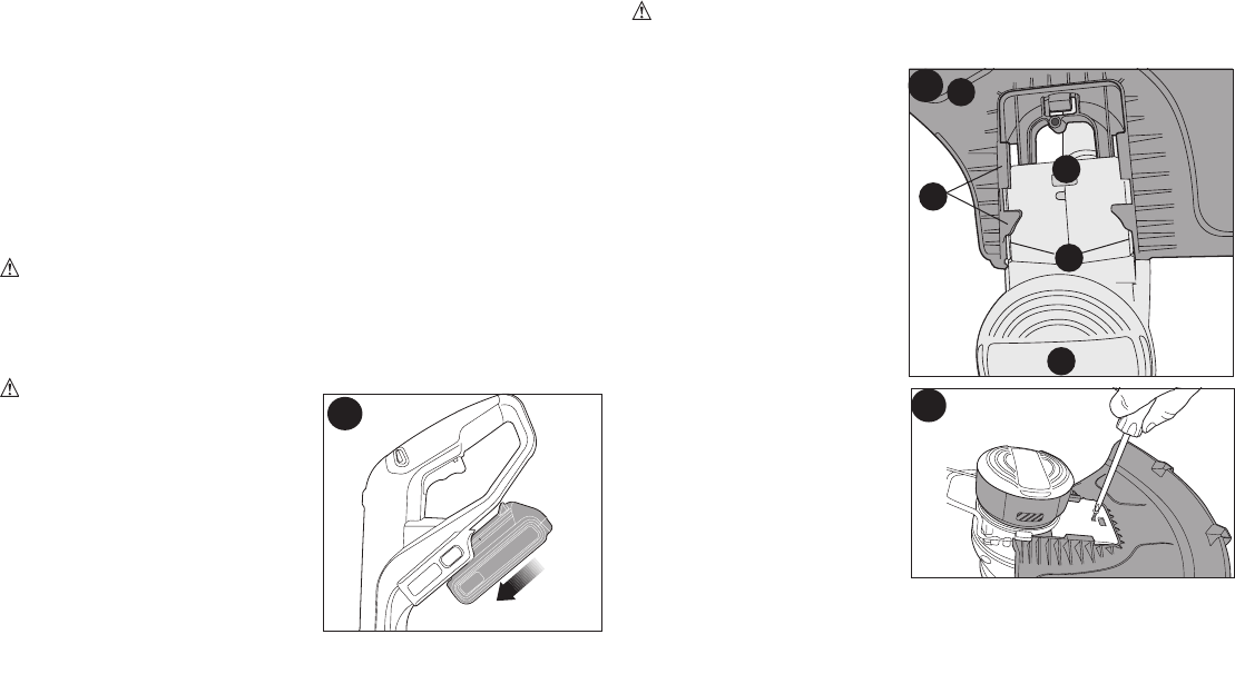
• Using a phillips screw-
driver, insert the guard
screw as shown in figure
4 to complete the guard
assembly.
• Once the guard is installed,
remove the covering from the
line cut-off blade, located on
the edge of the guard.
2
a
e
d
c
b
3
4