724-746-5500 | blackbox.com724-746-5500 | blackbox.com 724-746-5500 | blackbox.com
45° Side-Exiting Multmedia Panel 45° Side-Exiting Multmedia Panel45° Side-Exiting Multmedia Panel
Page 3Page 2 Page 4
JPMT1024-ANG JPMT1024-ANGJPMT1024-ANG
2.2 What’s Included
Your package should include the following items.
If anything is missing or damaged, contact Black Box
Technical Support at 724-746-5500 or
info@blackbox.com.
• (1) 45° Side-Exiting Multimedia Patch Panel
• (2) side brackets
• (1) rear cable bar
• (24) cable ties
• (4) 10-32 screws
• (4) 12-24 screws
• This user’s manual
3. Installation Steps
1. Mount the panel on a 19-inch rack, as shown
in Figure 1.
Figure 1. Mounting the panel on a rack.
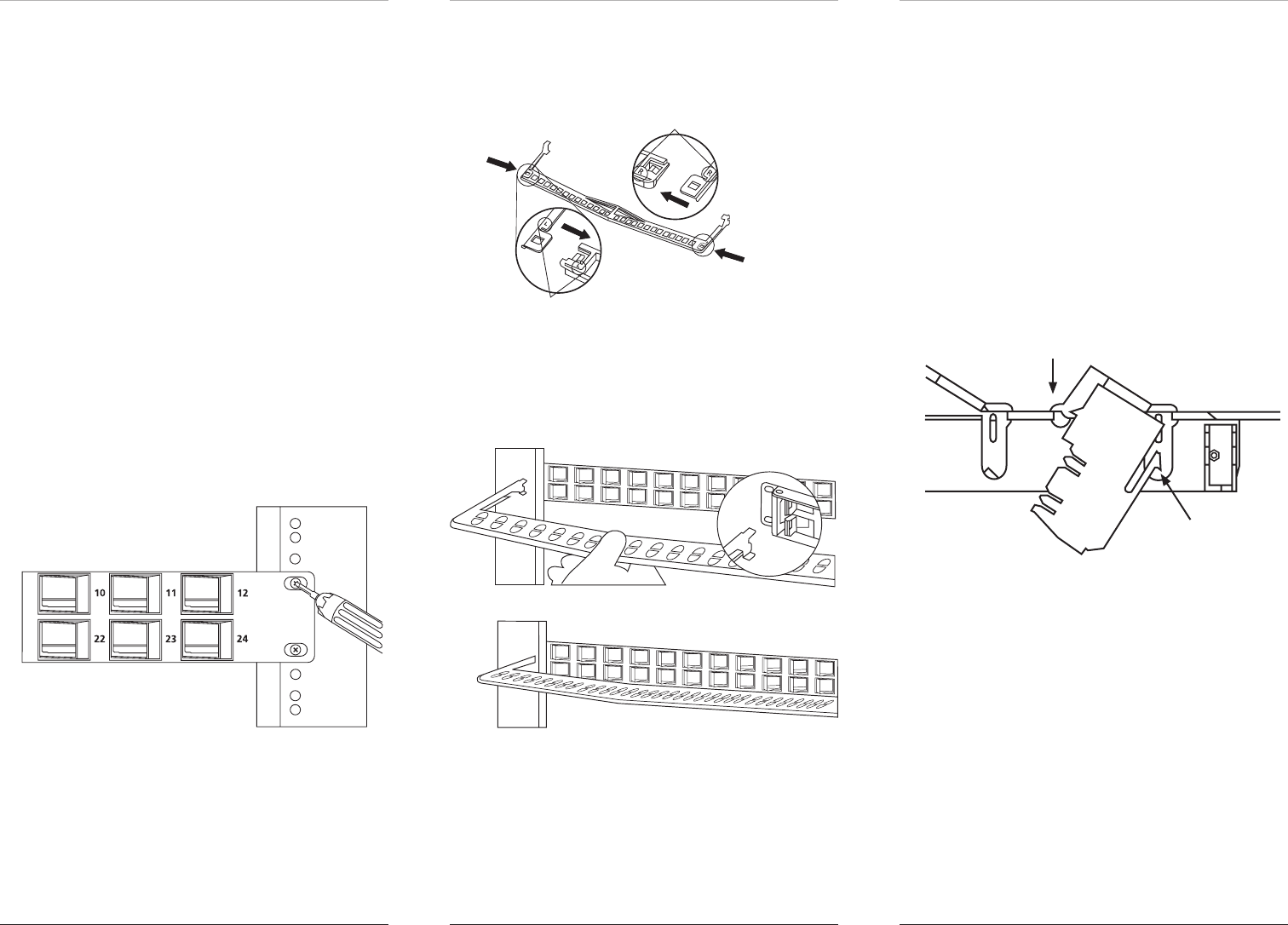
2. Attach each side bracket to the matching end of the
bar accordiing to the same marking. See Figure 2.
Slide in
Slide in
mark “L”
mark “R”
Figure 2. Attaching the side bracket.
3. Snap the rear cable bar into the patch panel, as
shown in Figure 3.
Figure 3. Attaching the rear wire manager.
4. Load the wired keystone jack into the patch panel.
Make sure the locking knob is locked first before
sliding in the keystone jack or support fitting. See
Figure 4.
NOTE: Ports 1–6 and 13–18 share the same orienta-
tion, while ports 7–12 and 19–24 are placed
in opposite positions. Be sure to follow the
directions during installation.
NOTE: For best connector loading sequences, start
from the sides and install toward the center.
locking knob
latch
Figure 4. Loading the keystone jack or support fitting.
5. Make sure the IDC slot of the keystone jack faces
toward the center of the patch panel, as shown in
Figure 5.


