


724-746-5500 | blackbox.com
Page 3
24- and 48-Port Category 6A Staggered Patch Panels User Manual
Assembly Instructions
1. Terminate the individual GigaTrue Category 6A jacks using the instruction sheets supplied with those products.
NOTE: Do not install Category 6A jacks onto the panel first.
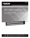
2. Insert the terminated jacks into the unloaded adapter panel. See Figure 1.
1
13
6
18
2
14
3
15
4
16
5
17
7
19
12
24
8
20
9
21
10
22
11
23
Category 6A
GigaTrue Category 6A
Staggered Patch Panel
(C6AMP70-24)
GigaTrue Category 6A jack
Figure 1. Installing the Category 6A jacks into the patch panel.
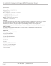
3. Without using the cable management bar, mount the panels in a standard 19" relay rack using the supplied hardware. See
Figure 2.
1
13
6
18
2
14
3
15
4
16
5
17
7
19
12
24
8
20
9
21
10
22
11
23
Category 6A
#12-24 or #10-32
cuphead Phillips
screws
(supplied)
#12-24 or #10-32
cuphead Phillips
screws
(supplied)
GigaTrue Category 6A
Staggered Patch Panel
(C6AMP70-24)
19" rack
Figure 2. Installing the patch panel onto a rack.
Using the Cable Management Bar
1. Remove the two cuphead screws from the rear side of the patch panel.
2. Position the cable management bar on the patch panel and reinstall the two cuphead screws to secure the cable management
bar.
3. Place the horizontal cable in one of the panel’s rear ports. Unscrew the corresponding silver clip behind the installed port and
position the horizontal cable under the silver bracket. Tighten the screw.
4. For a 48-port patch panel (C6AMP70-48), repeat Steps 1 through 3 to install the second cable management bar.