


Part No. 430258 Form No. F042099A
Page 3 of 8
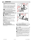
For your safety and the safety of others, these directions should be followed:
Use of Ear Protection is recommended while
operating this machine.
Do not operate this machine without first reading
owner's manual and engine manufacturer's manual.
Use of Eye and breathing protection is recom-
mended when using this machine, especially in
dry and dusty conditions.
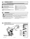
GENERAL SAFETY
9
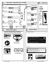
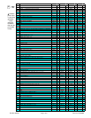
PACKING CHECKLIST
11
·DO NOT place hands or feet inside air intake opening, near
exhaust outlet or near any moving parts.
·DO NOT start engine without deflector attached to exhaust
outlet.
PUT OIL IN ENGINE BEFORE STARTING
Read all safety and operating instruc-
tions before assembling or starting this
unit.
10
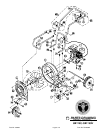
ASSEMBLY
Your Billy Goat is shipped from the factory in one carton,
completely assembled except for the upper handle assembly,
handle brace, plate deflector and throttle control.
These items should be included in your carton.
If any of these parts are missing, contact your
dealer.
Boxing Checklist
Denotes parts found in
Parts Bag Assembly
(shown on page 4).
Handle Upper
Assembly
400957
Check
Handle Brace
400951
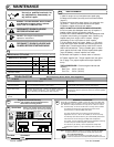
·DO NOT direct exhaust outlet toward any bystanders.
·DO NOT operate this equipment without first inspecting
work area.
·DO NOT operate this equipment during excessive vibration.
·DO NOT start engine without housing front plate attached.
·DO NOT operate this machine on slopes greater than 20%.
·DO NOT blow any hot or burning debris, or any toxic or
explosive material.
·DO NOT allow children to operate this equipment.
1. Install upper handle (Item 28), to preassembled lower handle (item 29),
using two screws (Item 17), and two lock nuts, (Item 32). Hand tighten only.
2. Install front of handle brace (Item 30), to blower housing using one
screw (Item 17), one washer (Item 58) and one lock nut (item 32). Install
rear of handle brace (item 30) to upper handle vibration mounts using two
lock nuts (item 32). Hand tighten only.
3. Securely tighten all hardware listed above in steps 1 thru 2.
4. Attach throttle control assembly to inside of upper handle using screw
(item 15), lock nut (item 37) and clamp cables (item 20).
5.Connect spark plug wire.
Check
Check
Parts Bag &
Literature Assy
430256
Per Model
Parts Bag
& Litera-
ture Assy
Check
Briggs &
Per Model
Check
Engine
Manual
Per
Model
Briggs & Stratton
11 HP
Honda 8 & 11 HP
P/N 31ZH9602
00X31-ZH9-6020
English
Check
P/N 272848 English and
P/N MS2558 multi-lang
P/N 273131 English and
P/N MS2650 multi-lang