


Part No. 890034 Form No. F101000A
Page 9 of 12
MAINTENANCE continued
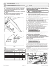
IMPELLER REMOVAL continued
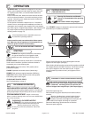
18. If chipper blade properly clears anvil surface, proceed to step .
If not, return to (step 14) and add or subtract shim washers as
needed to obtain a correct gap.
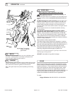
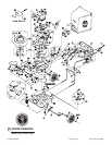
19. Reinstall engine and impeller onto housing in reverse order
of removal.
20. Before connecting spark plug wire, slowly pull engine
starting rope to insure that impeller rotates freely.
21. Reinstall spark plug wire.
fig. 7
17
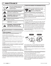
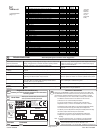
Engine (See Engine Manual)
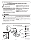
Check for excessive vibration
Clean Debris Bag
Check bag strap tightness
Inspect for loose parts
Maintenance Operation
Follow these hourly
maintenance intervals.
Maintenance Schedule
Inspect for worn or damaged parts
Every 5 hrs
or (Daily)
Every
Use
17.2
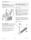
fig. 8
Rod
Control
Bracket
Clutch
121
Triangular
Plate
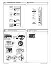
The clutch control cable is pre-adjusted at the factory, so when
the bail is released, rod (item 115), engages clutch assembly
(item 121), to stop forward drive motion and allow forward and
backward free-wheeling. When the bail is held against handle,
the clutch rod moves away from clutch assembly to allow drive
engagement.
If drive will not disengage, adjust and align control bracket so that
rod (item 115) fully contacts triangular plate on clutch assembly
when bail is released (see fig. 8).
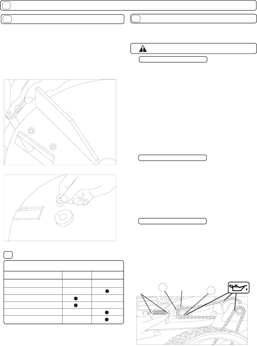
See lubrication intervals on Maintenance Schedule.
1. Remove chainguard (item 118) and 3 screws
(item 81 & 71).
2. Inspect chains (items 87 & 88), for wear, (see chain replace-
ment), lubrication and correct adjustment.
3. If adjustments are required, loosen 4 carriage bolts (item 90),
that hold bearing brackets for jackshaft assembly.
4. Adjusting all (3) chains at same time is necessary and can be
done by pulling jackshaft (item 93), up and forward.
5. Tension chains - similar to bicycle chain tightness with
about 1/8” (3.2mm) deflection with light hand pressure mid-
way between sprockets. A slightly loose chain is better than an
over tightened chain. DO NOT over tighten.
6. With chains aligned and tensioned, and jackshaft (item 93),
square and level, tighten carriage bolts (item 90).
7. Completely rotate drive wheels around several times to
insure there are no excessively tight areas in the chain.
8. Repeat steps 4 thru 7 if chains need readjustment.
9. Reinstall chainguard (item 118).
1. With chain guard removed, loosen carriage bolts (item 90),
that hold jackshaft (item 93), and bearing plates (item 101).
2. To replace inner chain (item 88), remove jackshaft
assembly and install replacement chain.
3. To replace wheel chains (item 87), slide bearing plates
(item 101), toward engine to loosen chains. Remove front wheels.
Reinstall replacement chains with wheels and onto
jackshaft sprockets.
4. See steps 4 thru 7 for chain alignment and adjustment.
5. Reinstall chainguard (item 118).
CLUTCH ADJUSTMENT
CHAIN ADJUSTMENTS
CHAIN REPLACEMENT
DRIVE
Chains are normal replaceable wear items. A new chain
should not be used on worn sprockets. Sprockets should be
replaced when replacing chains.
Stop engine and disconnect spark plug
wire before making adjustments.
17.3
115
17.1
fig. 6