


Part No. 500264 Form No. F082704A
When replacing one belt the other should be inspected for
wear and replaced if worn. It is good practice to change both
belts when either is worn beyond use. Use only original
equipment belts for replacement. Billy Goat uses only premium
quality, kevlar corded and coated belts in your unit. Substitute
belts do not meet the design and performance require-
ments for your unit , and will greatly reduce machine
performance and belt life.
Page 10 of 12
Use only a qualified mechanic for
any adjustments, disassembly or
any kind of repair .
WARNING: TO AVOID PERSONAL INJURY, ALWAYS
TURN MACHINE OFF, MAKE SURE ALL MOVING
PARTS COME TO A COMPLETE STOP.
17
MAINTENANCE
RECONNECT SPARK PLUG WIRE, AND ALL
GUARDS BEFORE STARTING ENGINE.
DISCONNECT SPARK PLUG WIRE
BEFORE SERVICING UNIT.
Note: Blade, and drive belts are normal wear items.
These should be inspected on a regular basis and
replaced if worn.
BELT REPLACEMENT
17.2
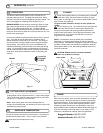
BLADE REMOVAL / SHARPENING
17.1
BLADE DRIVE BELT
NOTE: When sharpening the blade it is a good idea to check the
balance of the blade. A properly balanced blade will increase
life of the bearings and other components.
Tools required: 5/8 inch socket, torque wrench, adequate support.
1. Disconnect spark plug wire.
2. Support front of unit to allow access to the blade. Note: Unit
is heavy. Be sure support is adequate to prevent personal injury.
3. Block the blade to prevent it from rotating during removal.
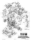
4. Remove the blade bolt (Item 139), lockwasher (140), and
large friction washer (54).
5. Remove the blade (50) and, replace or sharpen the blade.
NOTE: When replacing the blade use only B.G.I. Part no.
500210.
6.Replace the blade using all fasteners in the exact order
they were removed. Torque blade screw to 60 ft-lbs. NOTE:
Before installing the fasteners inspect them for wear and
replace as necessary.
Tools required: 1/2 inch socket, 1/2 inch universal extension bar, pry bar
or long screw driver, adequate support for machine.
1. Disconnect spark plug wire.
2. Support rear of unit to allow access to underside of the machine
towards the rear. Note: Unit is heavy. Be sure support is adequate to
prevent personal injury.
3. Remove the two screws (103) and washers (141) holding the engine
base door (7), and remove the door.
4. Loosen but do not remove the two nuts (116) holding the plate mount
idler (item 26) in place. This will release the tension on the blade drive
belt (29). NOTE: It may be necessary to apply some force to the pulley
to slide it over from it’s tight position and release the belt.
5. Working from the underside of the machine, loosen but do not remove
the four screws (103) holding the two belt guides(Items 149 & 150) in
place next to the crankshaft drive pulley (9) at the rear of the machine.
TRANSAXLE DRIVE BELT
Tools required: 1/2 inch socket, 1/2 inch universal extension bar, pry
bar or long screw driver, adequate support for machine.
1. Disconnect spark plug wire.
2. Support rear of unit to allow access to underside of the machine
towards the rear. Note: Unit is heavy. Be sure support is adequate to
prevent personal injury.
3. Loosen but do not remove the two nuts (116) holding the plate
mount idler (item 26) in place. This will release the tension on the
blade drive belt (29). NOTE: It may be necessary to apply some force
to the pulley to slide it over from it’s tight position and release the belt.
4. Working from the underside of the machine, loosen but do not
remove the four screws (103) holding the two belt guides(Items 149
& 150) in place next to the crankshaft drive pulley (9) at the rear of
the machine. This will loosen the belt guides(Items 149 & 150) and
allow them to move to the side. NOTE: This step requires the use of a
universal joint or universal extension bar to reach the screws(103)
holding the belt guide(149). If universal joint is not available you may
remove the “neutral stop bolt”(Item 115) and associated nuts (116 &
117) to allow the idler arm to swing back and allow access to the
screws(103) holding the belt guide(149).
5. With the guides loose slip the transaxle drive belt(Item 10) out of
the groove on the drive pulley and down past the pulley.
6. Slip the old belt(10) up and over the pulley on the transaxle (Item
9) and remove belt from machine.
7. Install new belt in groove on transaxle pulley(Item 9) and slip into
groove on transaxle drive pulley(46).
8. Tighten four screws(103) to secure belt guides(149 & 150) in place.
Note: With clutch levers engaged, be sure belt guides do not touch
belts after installation.
9. Reconnect spark plug wire.
WHEN POWER WASHING, DO NOT SPRAY
DIRECTLY ON THE BLADE CLUTCH.
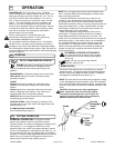
WHEEL DRIVE CLUTCH ADJUSTMENT
As the belt wears, adjustments may be required to maintain proper
control cable tension, and clutch engagement. If the belt begins
slipping or squealing during normal operation it may require an
adjustment to increase the clutch cable (item 18) tension. A
properly adjusted wheel drive clutch should require a minimum of
3 lbs. of force to completely depress the end of the clutch lever.
Clutch cable tension adjustment is located at the back of the
engine base. To increase tension adjust the cable so that more of
the adjusting barrell is exposed on the outside of the machine. To
decrease tension adjust the barrell in the opposite direction. When
replacing a belt be sure to check that it is properly tensioned.
Tip: To prevent wheels from seizing to axles remove
them once per season and coat the axles with anti-seize
compund. This should be done more often if using a
pressure washer to clean the unit regularly.