10
CONNECTION INFORMATION
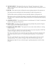
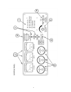
Your new Baldor Generator has all interconnecting wiring terminated at a junction box. All wiring will be
clearly labeled as being load; remote start contacts and AC input terminals and are to be connected as
described below.
Load – These connections are rated and sized according to the KW of the generator. Proper lead
wire from these points to the automatic transfer switch (or load switching device) is mandatory.
See enclosed transfer switch information for corresponding generator input terminals.
Remote Start Contacts – This two–wire connection, once connected to an appropriate switch,
will start the generator and perform as described in the remote start/stop literature. These
contacts are connected to the “Engine Start Contacts” of the automatic transfer switch.
A Two Pole normally open, closed to operate switch may also be used to start the generator.
AC Input – These connections are for units with float type battery chargers or engine block
heater combinations. A Constant supply of 120 volts AC (or as specified) is needed at these
terminals to power these devices.
NOTE: Power is not required when the unit is in operation. Internal battery charging and radiant heat
during operation eliminate the need for these devices.
NOTE: It is recommended that units utilizing an automatic transfer switch with adjustable time delays
have the initial adjustments made prior to start–up.
Factory recommendations are; allow a 2 second delay on start–up, 15–second delay on emergency to
normal.
Revised: March 20,2001 D:\ISO9001\FORMS\MSW’98bbk
Effective: April 23, 1999
Form#: S–PSG–001–19


