


3-4 Receiving & Installation MN2413
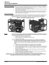
Fuel Connections
Before installing the fuel supply piping, check local and state codes that govern the use,
application and installation of gaseous fuel supplies. These regulations in addition to the
standards set by the National Fire Protection Agency (NFPA) should always be followed for a
safe, dependable and correct installation. The following NFPA regulations should be reviewed:
#37 Combustion Engines
#54 Gaseous Appliances and Piping
#58 Storage and Handling of LPG
These publications can be ordered from:
The National Fire Protection Agency
P.O. Box 9101
Quincy, MA 02269
WARNING: Incorrect installation of this generator set could result in property damage, injury or death.
Connection of the generator to its fuel source must be done by a qualified professional
technician or contractor.
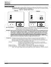
If natural gas supply is used, follow the “Natural Gas Connections” procedure. If Propane (LPG)
supply is to be used, follow the LP Gas Connections.
General Considerations
Pipe Size
Pipe sizecalculations are based on fuel consumption of an engine which is approximately 10,000
BTU’s needed per horsepower per hour. For example, a 10 horsepower engine requires 100,000
BTU’s of gaseous fuel per hour. Operating on natural gas which contains 1,000 BTU’s per cubic
foot, this engine would require 100 cubic feet of natural gas per hour to operate properly. In
addition to fuel consumption, the following factors must be considered when installing the
gaseous fuel supply piping:
1. Pressure loss due to the number of fittings (elbows, reducers, etc.)
2. Specific gravity of the gaseous fuel.
3. Pressure loss due to the length of the fuel supply piping.
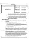
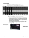
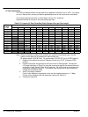
Table 3-1 lists the flow rate of natural gas in pipes of various diameters and lengths. The flow
rate (cubic feet per hour) and a pressure drop of 4” of water column compensates for a nominal
number of fittings and metering equipment.
Referring to the fuel consumption figures, we can use this chart to calculate proper sizing. For
example, if the engine is located 30 feet from the main fuel source’s primary regulator and the
engine needs 100 cubic feet of natural gas per hour, you can easily determine that the pipe size
must be at least 3/4 inch to deliver the volume of fuel necessary for the engine to operate
properly.
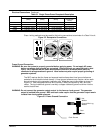
Primary Regulator (not supplied)
Provides initial control of fuel pressure as the fuel leaves the transmission line (natural gas), or
storage tank (LPG). The primary regulator distributes line pressures to more workable pressures
ranging from 4 to 6 ounces (approximately 11” of water column). A natural gas supplier may
boost pressure somewhat to achieve even distribution. However these pressures are usually
under 50 PSI. For this reason, the primary regulator used with natural gas systems does not
have to regulate the high pressures normally associated with LP gas systems.
Secondary Regulator (supplied)
Provides the final control of fuel pressure to the carburetor. This regulator is frequently referred
to as the Low Pressure Demand Regulator.
LP Tanks
The fuel supply must be adequate in order to meet the customer’s needs. The fuel tank must
meet all requirements set forth by local and state regulations. Small cyliders normally store such
a small amount of fuel that it has to be refilled every 4 to 7 hours.
Fuel Valves
In addition to the Fuel Lock–Off Kit, an LPG system should include a manually operated safety
shut–off valve located close to the fuel source. This valve may well be a valve located on the
tank itself or it may be a valve installed in the fuel transmission line. A manual shut–off valve is
often required by existing regulations in many localities.
The secondary demand regulator supplied with this generator set is designed to close and stop
fuel when the engine is not running. However, a ruptured diaphragm or a piece of dirt in the
regulator could prevent the valve from seating and should not be relied upon.