


Receiving & Installation 3-3MN2418
Electrical Connections All load connections are made at the panel using electrical cords with the proper
mating plug for the receptacle being used. More than one receptacle can be used as long as the
total load does not exceed the continuous rating of the generator.
WARNING: Never connect this generator to any buildings electrical system unless a licensed electrician
has installed an approved transfer switch. The National Electrical Code (NEC) requires that
connection of a generator to any electrical circuit normally powered by means of an electric
utility must be connected by means of approved transfer switch equipment so as to isolate
the electrical circuit from the utility distribution system when the generator is operating.
Failure to isolate the electrical circuits by such means may result in injury or death to utility
power workers due to backfeed of electrical energy onto the utility lines.
Use correct size insulated wire to connect the generator to the load. The gauge of the wire will
depend on the distance to the load, the permissible voltage drop at the load, and the current
required by the load. If you are not sure of the gauge wire needed for your application, consult a
competent electrician. Using wire that is too small can result in fire hazard. Also, be sure the
wire has the appropriate ratings for insulation and environment conditions.
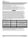
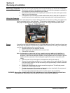
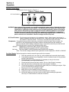
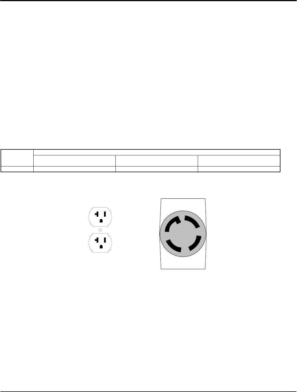
The correct mating connector must be used to fit the connectors provided on the operator panel
of your generator. Table 3-1 describes the connector types provided (receptacles) and the load
characteristics to help you choose the correct size wire. Figure 3-2 shows the receptacles.
Table 3-1 Single Phase Power Receptacle Description
Model Electrical Connection Information (Receptacle Provided at Panel)
Straight 120VAC
(20Amp)
Twist Lock 120/240VAC
(30Amp)
Rated Watts/
(Full load Amps 120/240)
PG6000 2− 520R 120VAC 1− L1430R 120/240VAC 5700 / (44.2/22.1)
Class 1 wiring methods must be used for field wiring connections to terminals of a Class 2 circuit.
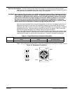
Figure 3-2 Receptacle Connections
(GOLD)
X
G
W
(SILVER)
Y
(GOLD)
NEMA
L14−30R
125/250V
30A
NEMA 520R
125V 20A
Ground
Neutral120VAC
120VAC