


Receiving & Installation 3-3MN2414
Electrical Connections Continued
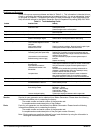
Table 3-1 Single Phase Power Receptacle Description
Model Electrical Connection Information (Receptacle Provided at Panel)
Straight 120VAC
(20Amp)
Twist Lock 120VAC
(30Amp)
Twist Lock 120/240VAC
(30Amp)
Twist Lock 120/240VAC
(50Amp)
Rated Watts/
(Full load Amps 120/240)
DG3E 2− 5−20R GFCI 120VAC 1− L5−30R 120VAC 1− L14−30R 120/240VAC 3300 / (25.0/12.5)
DG6E 4− 5−20R GFCI 120VAC 1− L5−30R 120VAC 1− L14−30R 120/240VAC 6000 / (50.0/25.0)
Note: GFCI is Ground Fault Protected power.
Class 1 wiring methods must be used for field wiring connections to terminals of a Class 2 circuit.
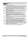
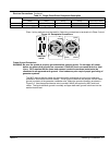
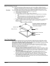
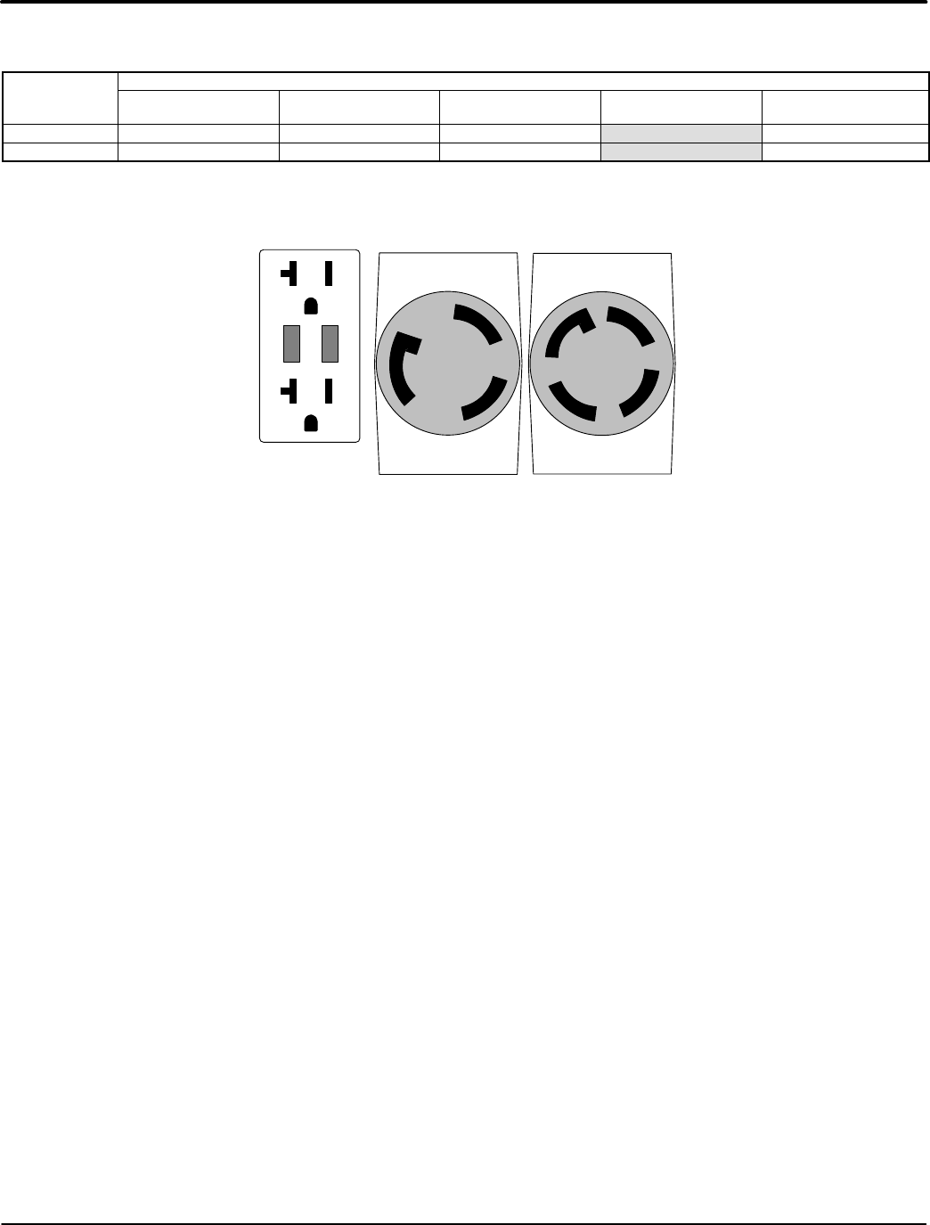
Figure 3-2 Receptacle Connections
X
(GOLD)
G
W
(SILVER)
NEMA
L5−30R
125V
30A
(GOLD)
X
G
W
(SILVER)
Y
(GOLD)
NEMA
L14−30R
125/250V
30A
NEMA 5−20R
125V 20A
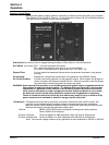
Frame Ground Connection
WARNING: Be sure the system is properly grounded before applying power. Do not apply AC power
before you ensure that grounds are connected. Electrical shock can cause serious or fatal
injury. NEC requires that the frame and exposed conductive surfaces (metal parts) be
connected to an approved earth ground. Local codes may also require proper grounding of
generator systems.
The NEC requires that the frame and exposed metal surfaces be at local ground reference
potential to avoid electrical shock hazard. A local ground reference may require a driven earth
ground conductor at the generator installation site. Make the ground connection as shown in
Figure 3-3. Use the appropriate size wire (normally 6 AWG) as required by NEC and local
codes. The local reference ground is normally a copper clad earth ground rod driven into the
earth at least 8 feet.