


C-4 Series AE11 MN2415
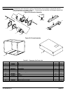
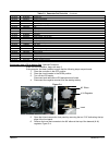
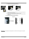
7. Remove the insert from the 90° elbow, Figure C-5.
8. Connect the hose and hose clamp to the 90° elbow.
Figure C-5
90° Elbow with LPG
Insert removed.
Insert
Hose (fuel line) and
clamp installed
9. Remove the control box cover by removing the six 7/16” bolts. to gain access to the
customer connection terminal strips.
10. Remove the jumper assembly attached to the demand regulator.
11. Locate the two terminals labeled FUEL JUMPER and connect the jumper assembly
between them.
12. Install the control box cover and the front panel.
The unit has now been converted to operate on Natural Gas.
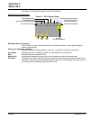
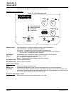
Figure C-6
Jumper attached
to K−N Regulator
L1 GEN
L2 GEN
L3 GEN
N GEN
G GEN
Grounding
Electrode
Terminal
N
L1 BAT Charger
N BAT Charger
G BAT Charger
Remote Start
Remote Start
Fuel Jumper
Fuel Jumper
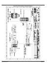
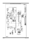
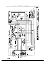
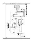
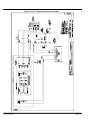
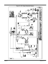
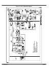
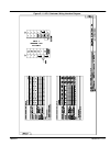
Wiring Diagrams Wiring diagrams for these generators are contained on the following pages of this appendix.