


GB - 35
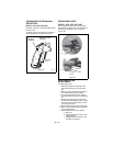
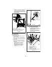
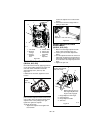
3. Pull idler away from traction drive belt
and remove belt from idler pulley, engine
sheave and driven pulley (it may be
necessary to turn engine pulley using
recoil handle).
4. Install new traction drive belt onto driven
pulley and engine sheave.
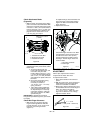
5. Swing drive plate toward friction disc
until finger lines up with stop hole in
frame. Slide drive plate over, inserting
finger into stop hole. Reinstall drive plate
spacer.
NOTE: Make sure the drive plate assembly
return spring remains connected to the frame
and nylon bushing is in drive plate pivot hole.
6. Replace attachment drive belt (See
Attachment Drive Belt Replacement on
page 33).
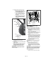
FRICTION DISC REPLACEMENT
1. Shut off engine, remove key, disconnect
spark plug wire and allow unit to cool
completely.
2. Place unit into service position on a level
surface.
3. Remove both wheels.
4. Remove bottom cover by removing six
hex bolts.
5. Disconnect pivot pin from the speed
selector arm. Save the hardware for
reinstallation.
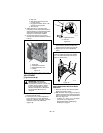
6. Remove spring clip pin nearest drive
sprocket from hex shaft.
7. Remove left bearing flange from frame.
8. Slide hex shaft to the left to remove
pinion sprocket and friction disc
assembly from hex shaft.
NOTE: Be sure to save washers between
bearing and sliding fork for re-assembly.
9. Remove friction disc assembly from
frame.
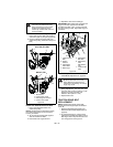
10. Remove three screws holding friction
disc to carrier bearing.
11. Remove old friction disc. Put the new
friction disc in place, cup side to carrier
bearing.
12. Reinstall three screws onto new friction
disc and carrier bearing. Torque to
5 – 6 lbf-ft (22.2 – 26.7 N•m).
13. Insert new friction disc assembly into
frame. Install washers onto carrier
bearing and slide into speed selector
arm.
14. Slide hex shaft through new friction disc
assembly. Install pinion sprocket onto
hex shaft and slide shaft into right
bearing.
15. Install left bearing using hardware
removed in step 7.
16. Reinstall clip pin into hex shaft.
17. Connect pivot pin to speed selector arm
(see Discharge Chute on page 29).
18. Replace bottom cover.
19. Install wheels.
20. Return unit to upright position.
21. Connect spark plug wire to spark plug.
22. Adjust traction drive clutch (see Traction
Drive Clutch Adjustment on page 32).
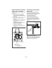
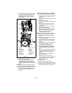
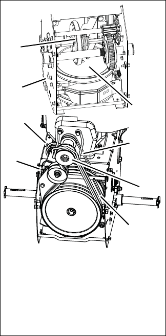
Figure 47
OS7144
1. Spacer
2. Drive Plate
Assembly
3. Traction Belt
Idler
4. Attachment
Drive Belts
5. Traction Drive
Belt
6. Engine
Sheave
7. Friction Disc
8. Drive Plate
Finger
2
3
5
6
1
7
4
8