


22
TO ADJUST STEERING WHEEL ALIGNMENT
If steering wheel crossbars are not horizontal (left to right)
when wheels are positioned straight forward, remove steer-
ing wheel and reassemble per instructions in the Assembly
section of this manual.
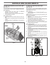
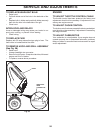
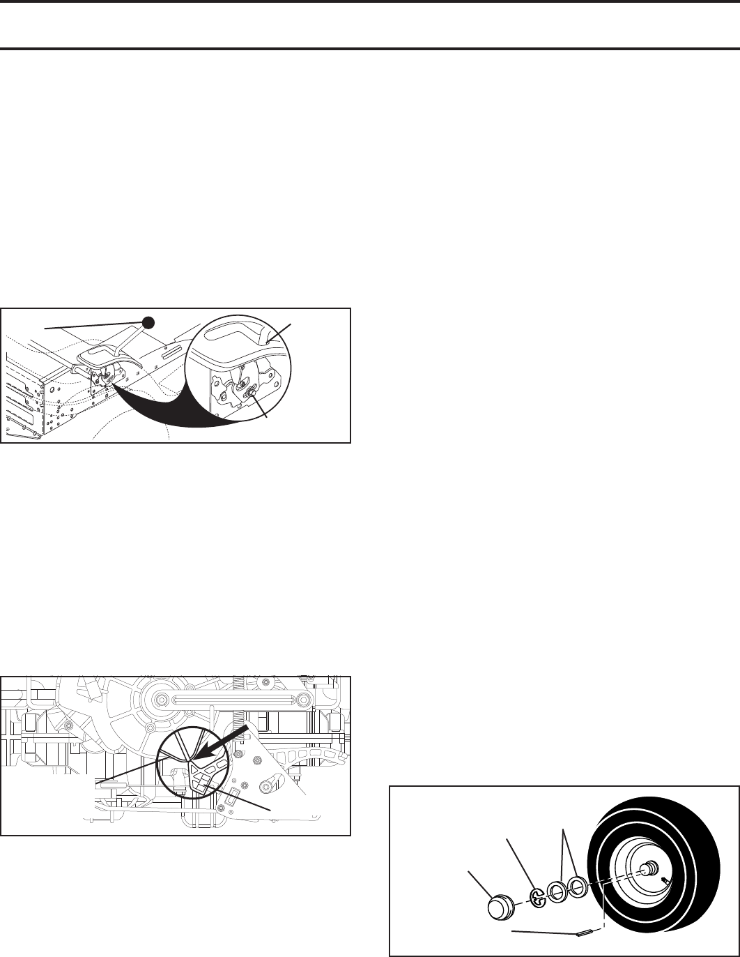
TO REMOVE WHEEL (See Fig. 35)
• Block up axle securely.
• Remove axle cover, retaining ring and washers to allow
wheel removal (rear wheel contains a square key - Do
not lose).
• Repair tire and reassemble.
• On rear wheels only: align grooves in rear wheel hub
and axle. Insert square key.
• Replace washers and snap retaining ring securely in
axle groove.
• Replace axle cover.
NOTE: To seal tire punctures and prevent flat tires due
to slow leaks, tire sealant may be purchased from your
local parts dealer. Tire sealant also prevents tire dry rot
and corrosion.
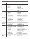
Fig. 35
RE TAIN ING
RING
WASH ERS
SQUARE KEY (REAR
WHEEL ONLY)
AXLE
COVER
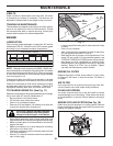
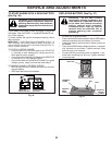
TRANSAXLE MOTION CONTROL LEVER
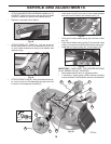
NEUTRAL ADJUSTMENT (See Fig. 33 and 34)
The motion control lever has been pre set at the factory
and adjustment should not be necessary.
• Engage the freewheel control lever. (See "TO TRANS-
PORT" in the Operations section of this manual.)
• Move the motion control lever until the unit rolls freely.
• While holding motion control lever in place, loosen the
adjustment bolt.
• Move motion control lever to the neutral (lock gate)
position.
• Tighten adjustment bolt securely.
NOTE: If additional clearance is needed to get to ad just ment
bolt, move mower deck height to the lowest position.
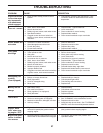
ADJUSTMENT
BOLT
NEUTRAL
LOCK
GATE
MOTION CONTROL
LEVER
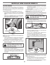
TRANSMISSION
TRANSMISSION
SHIFT PLATE
SHIFT PLATE
EXTRUSION
EXTRUSION
DYNAMIC
DYNAMIC
BRAKE ARM
BRAKE ARM
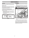
After above adjustment is made, if the tractor does not reach
full forward or reverse speed at the furthest motion control
lever location for forward and reverse, follow these steps.
• Lower attachment lift lever to it's lowest position.
• Move the shift plate on front of transmission so that
the extruded area centerline is in line with the dynamic
brake arm. (See Fig. 34)
• While holding motion control lever in place, loosen the
adjustment bolt.
• Move motion control lever to the neutral (lock gate)
position.
• Tighten adjustment bolt securely.
Fig. 33
Fig. 34
FRONT WHEEL TOE-IN/CAMBER
The front wheel toe-in and camber are not adjustable on
your tractor. If damage has occurred to affect the front
wheel toe-in or camber, contact your nearest authorized
service center/department.
TO CHECK BRAKE
If tractor requires more than five (5) feet to stop at highest
speed in high est gear on a level, dry concrete or paved
surface, then brake must be serviced.
You may also check brake by:
1. Park tractor on a level, dry concrete or paved surface,
depress brake pedal all the way down and engage
parking brake.
2. Disengage transmission by placing freewheel control
in “transmission disengaged” position. Pull freewheel
control out and into the slot and release so it is held in
the disengaged position.
The rear wheels must lock and skid when you try to manu-
ally push the tractor forward. If the rear wheels rotate,
then the brake needs to be serviced. Contact a qualified
service center.
SERVICE AND ADJUSTMENTS