


GB - 23
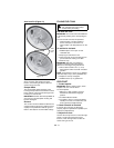
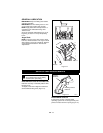
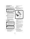
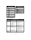
TRACTION DRIVE BELT
REPLACEMENT
NOTE: Housing and frame must be tipped
apart and attachment drive belt removed from
engine sheave in order to change traction
drive belt (Figures 18 and 19).
1. Remove attachment drive belt (See
Remove Attachment Drive Belt).
2. Pull idler away from traction drive belt and
remove belt from idler, camshaft pulley
and driven pulley (it may be necessary to
turn camshaft pulley using recoil starter
handle).
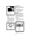
NOTE: To gain clearance, engage traction
clutch and if necessary pull back attachment
idler arm.
3. Replace traction drive belt making sure
pulleys align. If alignment is necessary,
loosen camshaft pulley set screws,
reposition pulley and retighten set
screws.
4. Replace attachment drive belt (See
Replace Attachment Drive Belt).
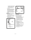
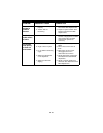
ATTACHMENT CLUTCH/BRAKE
ADJUSTMENT
1. Remove belt cover.
2. Check belt alignment (Figure 19).
Engine sheave and attachment pulley
must align vertically. Also, belt must be
centered in the idler pulley.
To align, move engine sheave:
a.Loosen set screws.
b.Slide sheave and key to desired
position.
c.Tighten set screws.
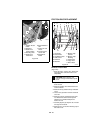
3. Adjust cable slack.
IMPORTANT: The clutch cable must be slack
when clutch bail is disengaged.
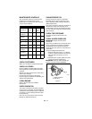
a.Center the upper cable adjuster on the
mounting bracket, if necessary
(Figure 20).
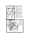
b.With the clutch bail disengaged,
loosen the control cable mounting nuts
on the attachment clutch arm
(Figure 23).
c.Pull up on the cable body to remove
cable slack.
d.Finger tighten mounting nuts and then
loosen the top nut five turns.
e. Tighten the bottom nut with a wrench.
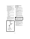
4. Check attachment clutch bail
measurement.
a. Start engine and run at full throttle.
b. Slowly squeeze the attachment clutch
bail until auger shaft begins to rotate.
c. Measure the distance from the end of
the clutch bail to the handlebar as
shown in Figure 22. The distance
between the clutch bail and the
handlebar should be 3-1/2 ± 1/8 in.
(8.9 cm ± 3 mm).
d. Shut off engine.
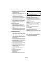
5. Adjust attachment clutch bail
measurement, if necessary.
a. Loosen idler nut (Figure 19).
b. To increase distance between clutch
bail and handlebar, move the idler
towards the attachment belt.
CAUTION: Always support Sno-
Thro frame and blower housing
when loosening the cap screws
holding them together. Never loosen
cap screws while unit is in service
position.
WARNING: IMPROPER
ADJUSTMENT could result in
unexpected movement of auger and
impeller causing death or serious
injury. AUGER / IMPELLER MUST
STOP within 3 seconds when
Attachment Clutch/Impeller Brake
Bail is released.
WARNING: Adjustment procedure
requires the engine to be run with
the belt cover off. AVOID INJURY.
Read and understand the entire
Safety section before proceeding.
Upper Cable
Adjuster
Figure 20
OS2460