


8 - 24
8.1 FRICTION WHEEL
1. To replace friction wheel, tip unit up onto housing
on a level surface.
2. Remove bottom cover by removing four cap
screws.
3. Remove right hand wheel, tire.
4. Remove bearing flange screws on the right hand
side of the frame. Remove bearing flange on frame
(Figures 16 and 17).
5. Remove the hairpin from the traction clutch rod
and disconnect traction drive lower linkage.
6. Remove cotter pin from traction clutch rod clevis
pin, pull rod from clutch fork arm and tip up and out
of the way.
7. Slide friction wheel assembly and hex shaft to right
until left end of hex shaft comes free of left bearing.
Slip assembly back to left and pull forward out of
frame.
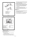
NOTE:
The 824 Models have a sprocket assembly with
chain drive. Slide the sprocket off the shaft and remove
(see Figure 19).
8. Remove three cap screws securing friction wheel
to hub and remove friction wheel.
9. Secure new friction wheel onto hub with three cap
screws and torque cap screws to 8-10 ft. lbs.
(10.8-13.6 Nm).
10.Place one of the washers onto the bottom bearing
flange pin and hold in place, rotate the hex shaft
with the friction wheel assembly into the housing.
11.Lift up on the shift arm assembly to gain clearance
between the drive plate and friction wheel. Align
the bearing assembly into the sliding forks placing
bottom flange pin into the forks first.
12.Place the other washer onto the top flange pin and
rotate it into the top fork. Be sure the washers are
on the inside of the forks.
NOTE:
On 824 Models install sprocket and bushing.
13.Slide hex shaft to left and into left bearing with flat
washers in position. Pinion gear must mesh with
the large gear. Ensure the flat washer is between
the bearing and the pinion gear.
14.Place the flat washer on the right end of the hex
shaft.
15.Install the bearing flange on the right side of frame.
16.Slide the traction clutch rod up and into the frame
and connect to the traction drive lower linkage with
clevis and cotter pin.
17.Reconnect the traction clutch rod to the lower
linkage.
18.Adjust traction drive clutch. Refer to Adjustments.
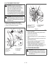
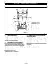
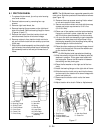
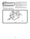
SECTION 8 - FRICTION WHEEL DRIVE
1. Hex Shaft
2. Bearing Flange
3. Sliding Forks
4. Friction Wheel
5. Drive Plate
6. Clutch Fork
7. Drive Pulley
8. Drive Belt
9. Idler Arm
10.Spring
11.Axle Shaft
12.Large Gear
13.Pinion Gear
14.Traction Clutch
Assembly
Figure 16
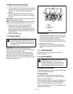
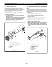
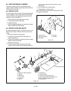
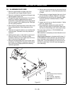
1. Cap Screw
2. Friction Wheel
3. Friction Wheel Shift
Arm
4. Idler Hex Shaft
5. Cotter Pin
Figure 17